
ORIGINAL PAPER
Effect of mass distribution on curving performance
for a loaded wagon
Duo Zhang .Yinying Tang .Qiyuan Peng .Chunjiao Dong .Yunguang Ye
Received: 24 February 2020 / Accepted: 17 March 2021 / Published online: 25 March 2021
ÓThe Author(s) 2021
Abstract The location of wagon gravity center for a
loaded wagon is underestimated in a vehicle–track
coupled system. The asymmetric wheel load distribu-
tion due to loading offset significantly affects the
wheel-rail contact state and seriously deteriorates the
curving performance in conjunction with the height of
gravity center and cant deficiency. Optimizing the
location of gravity center and cruising velocity,
therefore, is of interest to prevent the derailment and
promote the transport capacity of railway wagons.
This study aims to reveal the three-dimensional
influencing mechanism of mass distribution on vehicle
curving performance under different velocities. The
wheel unloading ratio is regarded as the evaluation
index. A simplified quasi-static model is established
considering essential assumptions to highlight the
influence of lateral and vertical offset on curving
performance. For a more accurate description, the
MBS models with various locations of wagon gravity
center are built and then negotiate curves in different
simulation cases. The simulation results reveal that the
distribution of wheel unloading ratio determined by
loading offset is like contour lines of ‘basin’. Based on
the conclusions of quasi-static analysis and dynamics
simulations, the regression equation is proposed and
the fitting parameters are calculated for each simula-
tion case. This paper demonstrates the necessity of
optimizing the location of wagon gravity center
according to the running condition and offers a novel
strategy to load and transport the cargo by railway
wagons.
Keywords Railway wagon Mass distribution
Curving performance Quasi-static analysis
Dynamics simulation Regression equation
1 Introduction
Symmetric distribution is the basic criterion for the
loading of cargo on wagons. It has been a consensus
that the optimal location of cargo gravity center is at
the center of the vehicle laterally and longitudinally.
D. Zhang Y. Tang Q. Peng
School of Transportation and Logistics, Southwest
Jiaotong University, Chengdu 610031, China
D. Zhang Y. Tang Q. Peng
National United Engineering Laboratory of Integrated and
Intelligent Transportation, Southwest Jiaotong University,
Chengdu 610031, China
C. Dong
Key Laboratory of Transport Industry of Big Data
Application Technologies for Comprehensive Transport,
Ministry of Transport, Beijing Jiaotong University,
Beijing 100044, China
Y. Ye (&)
Institute of Land and Sea Transport Systems, Technical
University of Berlin, 10587 Berlin, Germany
e-mail: [email protected]
123
Nonlinear Dyn (2021) 104:2259–2273
https://doi.org/10.1007/s11071-021-06386-3(0123456789().,-volV)(0123456789().,-volV)

Thus, the general wagon-rail models assume that the
wagon gravity center (WGC) is the same as its
geometry center in the horizontal plane [1–5]. Since
the uneven mass distribution could result in an obvious
unbalance of wheel load and deteriorate the curving
performance seriously, symmetric loading is the basic
prerequisite in the studies with respect to guaranteeing
wagon running safety [6–11].
However, according to practical experience, skew
loading cannot be avoided completely. For the sake of
vehicle running safety, loading guidelines of several
rail organizations are promulgated to specify the
allowed offset values:
(1) International Union of Railways (UIC) [12]
The ratio of masses per bogie should be less than
3:1 and the ratio of load between the wheels
(left/right) of a given axle should be less than
1.25:1. Moreover, the mass per axle should not
exceed the maximum axle load.
(2) The Association of American Railroads (AAR)
[13]
Longitudinally, the center of load weight should
have a certain distance from either truck center,
which depends on the ratio between load weight
and load limit. Laterally, the load must be
located to equalize the weight.
(3) Chinese Railways (CR) [14]
The transversal distance between the cargo’s grav-
ity center and the carbody’s geometrical center should
be within 100 mm. The difference between the masses
per bogie should be no more than 10 ton, and the mass
of cargo on either bogie should not exceed half of the
loading capacity of the wagon.
Depending on these three representative examples,
we can recognize that there are no universal require-
ments on the mass distribution for a loaded wagon.
Moreover, the allowed offset values stated in the
loading guidelines are sketchy and empirical to some
extent. For a further supplement to loading guidelines,
the method of dynamics simulation has been used to
search for the safe range of wagon’s gravity center.
Shatunov and Shvets [15] proposed that, as for a kind
of 4-axle flat wagon, the maximum lateral offset could
reach 150 mm and longitudinal offset could be
expanded too. Bao et al. [16] focused on a common
open-top wagon in China and demonstrated that CR
criteria were conservative.
The loading guidelines and limited former studies
are based on assumptions that the best location of the
cargo is at the center of a wagon and the height of
WGC should be as low as possible. There are two
confusions brought by the aforementioned documents
and their prerequisites:
(1) The location of the combined center of gravity is
a three-dimensional variable. The decision on
skew loading should be made combined with the
height of gravity center, which is neglected
when defining the allowed offset. Matsumoto
et al. [17] and Bekele [18] pointed out that
lowering the height of gravity center was an
obvious advantage for running safety. Zhang
et al. [19] attempted to figure out the three-
dimensional constraint for the combined center
of gravity of a loaded wagon but failed to draw a
quantitative conclusion.
(2) The assumption of optimal choice is not
convincible. Suda et al. [20,21] proposed that
the asymmetric truck may be better for curving
performance. Keropyan et al. [22] demonstrated
that a longitudinal offset was necessary for the
locomotive to promote its traction ability. Since
the advantage of asymmetric loading had been
proved in other areas, we can infer that
symmetric distribution might not be a perfect
plan for all the loading cases.
Since loading guidelines and former studies have
obvious limitations, this paper analyzes the stereo-
scopic influence mechanism of mass distribution for a
loaded wagon on its curving performance. It has been
demonstrated that the safety indices would be severe
when the wagon negotiates the transition curve (TC)
[19]. Optimizing the location of WGC on TC is
necessary to improve the curving performance. How-
ever, because of the geometry and changing elevation
of TC, it is difficult to reveal the quantitative
relationship between the location of WGC and the
curving performance on TC. Thus, the process of
negotiating the circular curve is the objective of this
study.
In Sect. 2, a simplified quasi-static analysis of an
uneven loaded wagon is conducted considering pro-
fuse assumptions. Section 3establishes the MBS
model and carries out simulations to discuss the
qualitative relationship between the location of WGC
and the selected safety criterion. Based on the
123
2260 D. Zhang et al.
conclusions in Sect. 3and Sect. 4proposes the
regression equation and calculates the fitting param-
eters for each simulation case.
2 Analysis of the vehicle curving performance
with a simplified quasi-static model
2.1 Quasi-static model
This paper focuses on the two-axle wagon with three-
piece bogies. There is no doubt that the suspension
system plays a key role in the vehicle running
performance by means of weakening the impact
between the carbody and wheelset. Nevertheless, as
for the unevenly loaded wagon, the suspension device
has little effect on inhibiting the unbalanced wheel
load which is resulted from the asymmetric mass
distribution and closely related to the vehicle running
safety. Thus, the quasi-static model is established to
highlight the influence of mass distribution on the
wheel load. The wagon in uniform circular motion is
deemed as suffering equilibrium force including the
centrifugal force so that it can be regarded as a whole.
In order to simplify the model, essential assumptions
are put forward as below:
(1) All the parts of the model are rigid bodies.
(2) The track is smooth and has no rail cant.
(3) The wheelset is symmetric with the center line
of the track.
(4) The load of a truck is distributed evenly to each
wheelset.
(5) The carbody is at its original position.
The mass distribution is directly related to the
vertical contact force. Consequently, the wheel
unloading ratio is more sensitive than the derailment
coefficient for this issue in terms of definitions. This
conjecture was demonstrated by Zhang et al. [19].
Thus, the quasi-static analysis emphatically reveals
the vertical contact force for each wheelset and regards
the wheel unloading ratio as the evaluation index.
In the X–Z plane of the coordinate system of track
centerline, the wagon can be regarded as a simply
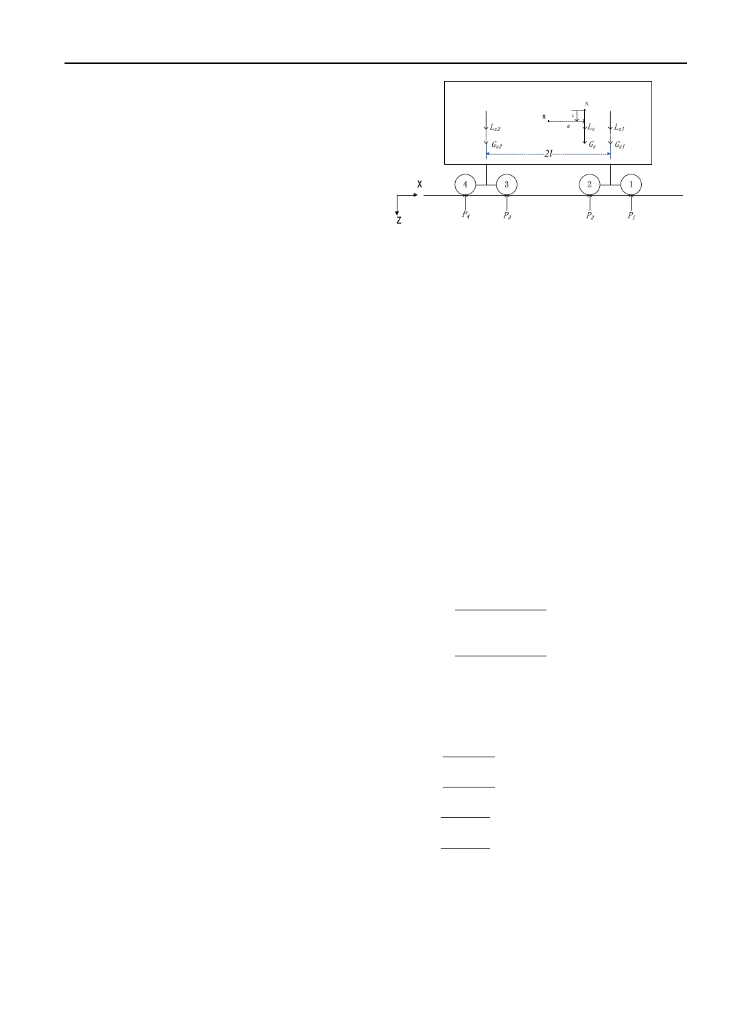
supported beam as is shown in Fig. 1.
where P
i
(i= 1,2,3,4) is the vertical contact force of
wheelset; lis half of the length between bogie pivot
centers; G
z
and L
z
are the vertical component force of
wagon’s gravity and centrifugal force, respectively;
G
zq
(q= 1,2) is distributed G
z
on each truck; L
zq
(q= 1,2) is distributed L
z
on each truck; M and N are
the geometrical center of the carbody and the gravity
center of the wagon, respectively; ais the longitudinal
offset; cis the vertical offset.
Since the wagon suffers vertical equilibrium force,
the sum of vertical contact force can be given by:
X
4
i¼1
Pi¼GzþLz:ð1Þ
Based on the torque balance, the sum of torques
around the rear truck center can be presented as
follows:
ðP1þP2Þ2l¼ðGzþLzÞðlþaÞ:ð2Þ
According to the assumptions, P
1
=P
2
,P
3
=P
4
.
Therefore, the vertical contact force can be calculated
based on Eqs. (1) and (2):
P1¼P2¼ðGzþLzÞðlþaÞ
4lð3Þ
P3¼P4¼ðGzþLzÞðlaÞ
4l:ð4Þ
Furthermore, as a simply supported beam, the
gravity force and centrifugal force are distributed on
the front and rear center plate as below:
Gz1¼GzðlþaÞ
2l
Gz2¼GzðlaÞ
2l
Lz1¼LzðlþaÞ
2l
Lz2¼LzðlaÞ
2l
8
>
>
>
>
>
>
>
>
>
<
>
>
>
>
>
>
>
>
>
:
:ð5Þ
The mass of wagon is distributed to each truck
longitudinally as already stated. Then, lateral offset
Fig. 1 Longitudinal mass distribution of a loaded wagon
123
Effect of mass distribution on curving performance for a loaded wagon 2261
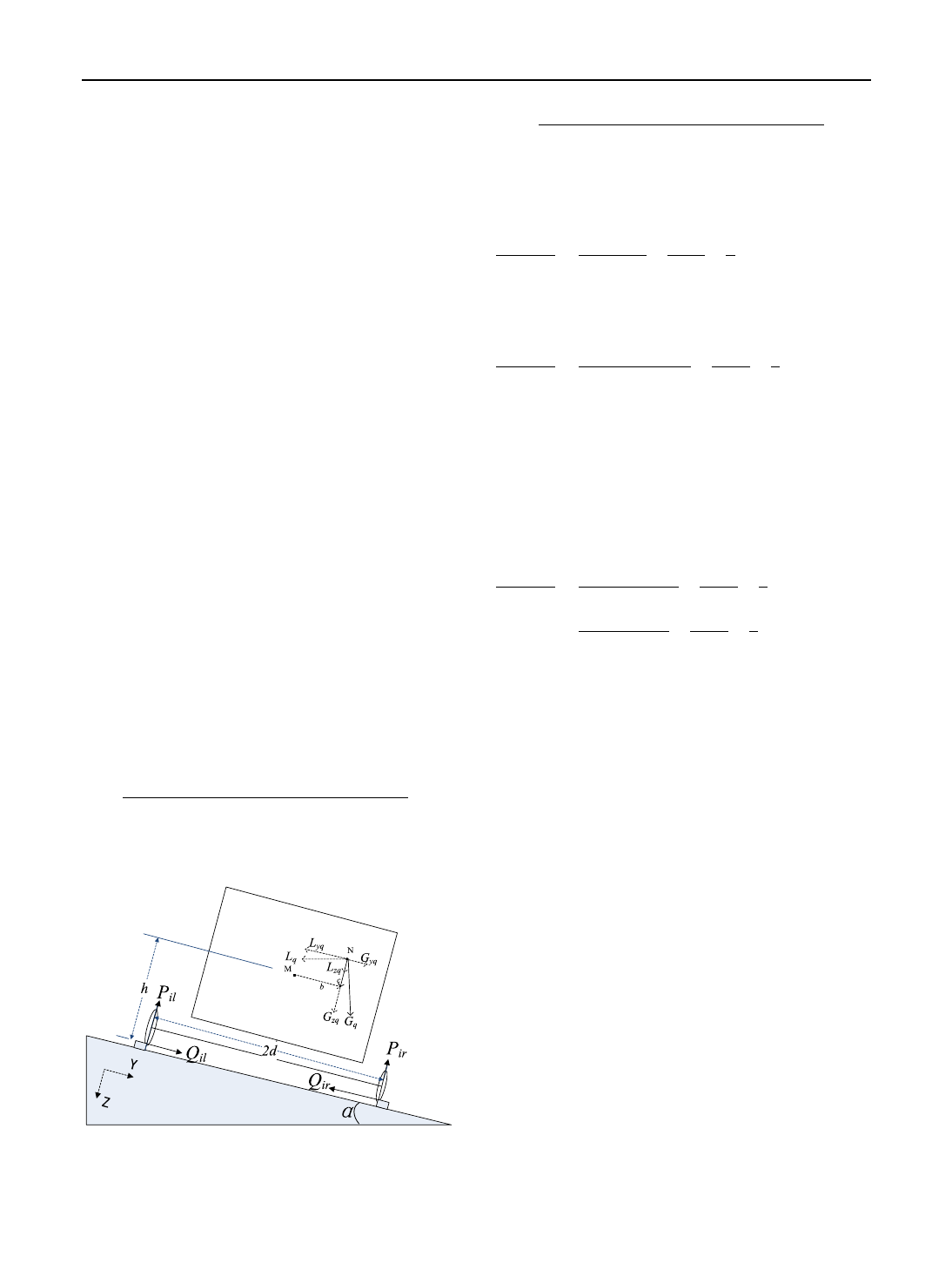
assigns the load of each wheelset to the wheels as
Fig. 2illustrates.
where G
q
and L
q
are the gravity and centrifugal
force of the mass loaded on the truck whose order is q,
respectively; subscript qdenotes the front truck when
its value is 1 and the rear truck when its value is 2; Pis
the vertical contact force; Qis the lateral contact force;
subscript idenotes the order of wheelset as is shown in
Fig. 1; subscript land rdenote the left and right wheel
of the wheelset, respectively; arepresents the angle
resulted from superelevation; bis the lateral offset; cis
the vertical offset from N to M; his the vertical
distance from M to the top of rail; dis the half of tape
circle distance. In this paper, we take the right-hand
curve as an example. It is easy to point out that:
i¼1;2q¼1
i¼3;4q¼2
:ð6Þ
As for the truck whose order is q(q= 1, 2), its
distributed vertical load is borne by the corresponding
wheelsets:
XPil þXPir ¼Gzq þLzq:ð7Þ
Moreover, the resultant moment of the truck can be
calculated as:
XPir 2dþðLyq GyqÞðhþcÞ
¼ðLzq þGzqÞðdþbÞ:ð8Þ
Based on Eqs. (6) and (7), the vertical contact force
can be presented as:
Pil ¼ðLzq þGzqÞðdbÞþðLyq GyqÞðhþcÞ
4dð9Þ
Pir ¼ðLzq þGzqÞðdþbÞðLyq GyqÞðhþcÞ
4d:
ð10Þ
For any wheelset, the wheel unloading ratio (UN)
can be derived as:
Pil Pir
Pil þPir
¼Lyq Gyq
Lzq þGzq
hþc
db
d:ð11Þ
Combined with the geometric relationship,
Eq. (11) can be derived as:
Pil Pir
Pil þPir
¼Lzq Gzq tan2a
tan aðLzq þGzqÞhþc
db
d:ð12Þ
Since we have assumed that the truck would
allocate its load to inclusive wheelsets evenly, wheel-
sets of the same truck have identical UN. According to
Eq. (10), it seems that the mass loaded on truck has
effect on the UN. For revealing the effect of the mass
distribution significantly, Eq. (5) is substituted to
Eq. (12) to obtain:
Pil Pir
Pil þPir
¼LzGztan2a
tan aðLzþGzÞhþc
db
d
¼v2gR tan a
v2tan aþgR hþc
db
dð13Þ
where vdenotes the vehicle running velocity; Rde-
notes the radii of curve; gdenotes the acceleration of
gravity.
2.2 Analysis of derivative results
Equation (11) illustrates that apart from the lateral and
vertical offset, cant deficiency affects the value of UN
significantly. The values of (h?c), dand Lzq þGzq
are definitely positive. Thus, the positive/negative
signs of Lyq Gyq
and bdetermine the trend of
change in the absolute value of UN as below:
(1) Lyq\Gyq,b[0orLyq [Gyq,b\0
The absolute value of UN is positively corre-
lated with |b| and c.
(2) Lyq\Gyq,b\0orLyq [Gyq,b[0
It is complicated to describe the trend of the
absolute value of UN since it is denoted as the sum of a
positive expression and a negative expression con-
taining variables. Numerical computation is needed to
reveal the distribution rules of UN.
Fig. 2 Lateral mass distribution of loaded wagon
123
2262 D. Zhang et al.
The difference between the lateral component
forces of centrifugal force and gravity of distributed
mass reflects cant deficiency, which is derived to
obtain Eq. (13). Based on Eq. (13), we can demon-
strate the relationship among the loading offset,
velocity and UN clearly. As an example, we assume
that tan aequals 0.1045, the gauge equals 1435 mm,
dequals 0.75 m. For a better description, we use the
variable of zto denote the sum of hand cand set the
scopes of zand b. When the loaded wagon negotiates
curves whose radii are 350 m and 600 m, respectively,
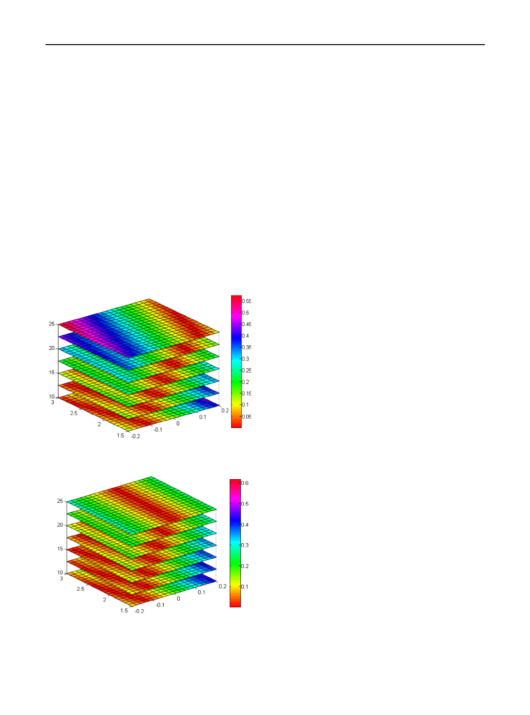
with velocities from 10 m/s to 25 m/s, the absolute
value of UN can be calculated as Fig. 3illustrates.
Figure 3reveals the influence of loading offset and
velocity on UN that can be concluded as below:
(1) For the selected velocity and curve radius, the
distribution of UN is similar as the contour lines
of ‘basin.’ With the increase in velocity, the
location of the basin moves to the right of the
wagon.
(2) For most locations, the absolute value of UN
increases with the increase in vertical offset. But
if there is a large negative offset laterally, the
absolute value of UN will decrease as the
vertical offset increases when the velocity is
low.
(3) The balancing velocity (m/s) can be calculated
as Eq. (14):
V0¼ffiffiffiffiffiffiffiffiffiffiffiffiffiffiffiffi
gR tan a
p:ð14Þ
For curves whose radii are 350 m and 600 m,
their balancing velocities are 19 m/s and 25 m/
s, respectively, based on Eq. (14). Figure 3
demonstrates that when the wagon negotiates
the curve at the balancing velocity, UN can be
constrained efficiently with the fluctuations of
lateral and vertical offset.
By means of quasi-static analysis, the roles of
lateral and vertical offset in UN can be revealed. In
order to demonstrate the conclusions of quasi-static
analysis and study the effect of longitudinal offset on
UN, dynamics simulation should be implemented.
3 Dynamics simulation
3.1 Dynamic equations of carbody
In this paper, we adopt C
70H
as the analysis object,
which is one of the commonly used open-top cars in
China. The MBS model of C
70H
is made up of cargo,
carbody and two three-piece bogies. The schematic
diagram is shown in Fig. 4.
where H
j
(j= 1, 2, 3) denotes the distance between
the gravity centers of different components; rdenotes
the rolling radius of the wheel; idenotes the angle
resulted from the superelevation; adenotes the tilt
angle of carbody; sdenotes half of the tape circle
distance.
Due to the loading offset, the dynamic equations of
carbody play a primary role in building the MBS
model of C
70H
. Because it is deemed that the bolster is
fixed with carbody in each degree of freedom except
roll, the carbody can be regarded as being exerted by
the lateral and vertical forces of the secondary
b (m)
z (m)
v (m/s)
Absolute value of UN
(a) R=350 m
b (m)
z (m)
v (m/s)
Absolute value of UN
(b) R=600 m
Fig. 3 Distribution of the absolute value of UN
123
Effect of mass distribution on curving performance for a loaded wagon 2263
Loading more pages...