IOP Conference Series: Materials Science and Engineering
PAPER • OPEN ACCESS
Influence of an external applied AC magnetic field
on the melt pool dynamics at high-power laser
beam welding
To cite this article: Ömer Üstünda et al 2021 IOP Conf. Ser.: Mater. Sci. Eng. 1135 012017
View the article online for updates and enhancements.
You may also like
Analysis of Influence of Impurities in
Hydrogen on PEFC Performance, Based
on Measurement of Current Distribution
Using Electrochemical Impedance
Distribution Analyzer
Takahide Haneda, Koki Watanabe and
Noboru Katayama
-
Effect of genetic and paratypical factors on
milk production in cattle
O E Lihodeevskaya, G A Lihodeevskiy, O
V Gorelik et al.
-
Field-aware User Influence
Recommendation Model Based on Trust
Relationship
Bai Yun and Cai Wandong
-
This content was downloaded from IP address 130.149.177.113 on 27/04/2022 at 16:38

Content from this work may be used under the terms of theCreativeCommonsAttribution 3.0 licence. Any further distribution
of this work must maintain attribution to the author(s) and the title of the work, journal citation and DOI.
Published under licence by IOP Publishing Ltd
18thNordicLaserMaterialsProcessingConference(18thNOLAMP)
IOPConf.Series:MaterialsScienceandEngineering 1135 (2021)012017
IOPPublishing
doi:10.1088/1757-899X/1135/1/012017
1
Influence of an external applied AC magnetic field on the melt
pool dynamics at high-power laser beam welding
Ömer Üstündağ1, Nasim Bakir1, Andrey Gumenyuk1,2, Michael Rethmeier3,1,2
1Bundesanstalt für Materialforschung und -prüfung (BAM), Unter den Eichen 87,
12205 Berlin, Germany
2Fraunhofer Institute for Production Systems and Design Technology, Pascalstraße 8-
9,
10587 Berlin, Germany
3Institute for Machine Tools and Factory Management, Technische Universität Berlin,
Pascalstraße 8-9, 10587 Berlin, Germany
oemer.uestuendag@bam.de
Abstract. The study deals with the determination of the influence of an externally applied
oscillating magnetic field on the melt pool dynamics in high power laser beam and hybrid laser
arc welding processes. An AC magnet was positioned under the workpiece which is generating
an upward directed electromagnetic force to counteract the formation of the droplets. To
visualise the melt flow characteristics, several experiments were carried out using a special
technique with mild steel from S355J2 with a plate thickness of up to 20 mm and a quartz glass
in butt configuration. The profile of the keyhole and the melt flow were recorded with a high
-
speed camera from the glass side. Additionally, the influence of the magnetic field orientation to
the welding direction on the filler material dilution on laser hybrid welding was studied with
variating oscillation frequency. The element distribution over the whole seam thickness wa
s
measured with X-ray fluorescence (XRF). The oscillation frequency demonstrated a great
influence on the melt pool dynamics and the mixing of the elements of the filler wire. The high
-
speed recordings showed, under the influence of the magnetic field, that the melt is affected
under strong vortex at the weld root, which also avoids the formation of droplets.
1. Introduction
Despite the availability of high-power laser systems within the range beyond 100 kW on the market, the
use of high-power laser beam welding (LBW) for thick metal sections at industrial scale are still under
discussion. Its application for plate thicknesses greater than 15 mm has certain technological limitations.
One of the limiting factors is the formation of sagging due to the gravitational forces or the hydrostatic
pressure often observed during welding in flat position (1G). For that reason, the arc-based welding
processes are usually implemented for welding of thick-walled structures with wall thicknesses above
15 mm. However, these are less productive as compared with high-power LBW cause of lower
penetration depth. Hence, multi-layer technology is used for welding of thick metal plates. It leads to
high heat inputs and distortion or thermal induced residual stress of the plates as well as reworks
hindrances such as flame straightening thus expend more time and cost.
Several investigations were conducted to identify the maximum boundaries of the single-pass high
-
power LBW or hybrid laser-arc welding (HLAW) and their challenges and physical backgrounds.
Similar challenges or defects are to be expected for high-power LBW or HLAW. Single-pass HLAW
18thNordicLaserMaterialsProcessingConference(18thNOLAMP)
IOPConf.Series:MaterialsScienceandEngineering 1135 (2021)012017
IOPPublishing
doi:10.1088/1757-899X/1135/1/012017
2
was produced up to 28 mm metal thickness using a laser power of just 19 kW with an electromagnetic
weld pool support system [1] or HLAW of 25 mm thick plates using cut-wire, which was filled within
an air gap between workpieces, with ceramic or flux backing and also up to 50 mm depth by double
sided welds approach showed successful outcomes [2]. Multilayer high-power LBW, especially HLAW
technique was demonstrated in [3] for one sided steel welds ranging in thickness from 28 mm to 32 mm
in two to five layers. Laser beam welding process under vacuum conditions [4,5], laser submerged arc
hybrid welding [6], or narrow-gap laser-arc hybrid welding [7] were conducted successfully for deep
penetration weld joints. As reported in the studies dealing with single-pass high-power LBW, the
formation of sagging or drop-outs is a major challenge during welding. Guidelines for preventing the
drop-outs were reported in [8], where the increase of the welding speed or laser power is recommended
for the prevention of those defects. The main physical background of this recommendation lies in the
fact, that with increasing welding speed the geometrical sizes of the seam is changed to thinner seam
width. This leads to the increase of the surface tension which counteracts the hydrostatic pressure on the
root part. Hence, the stability criterion is dependent on geometrical dimensions of weld seams and is
defined in conformance with [9] as shown in Equation 1:
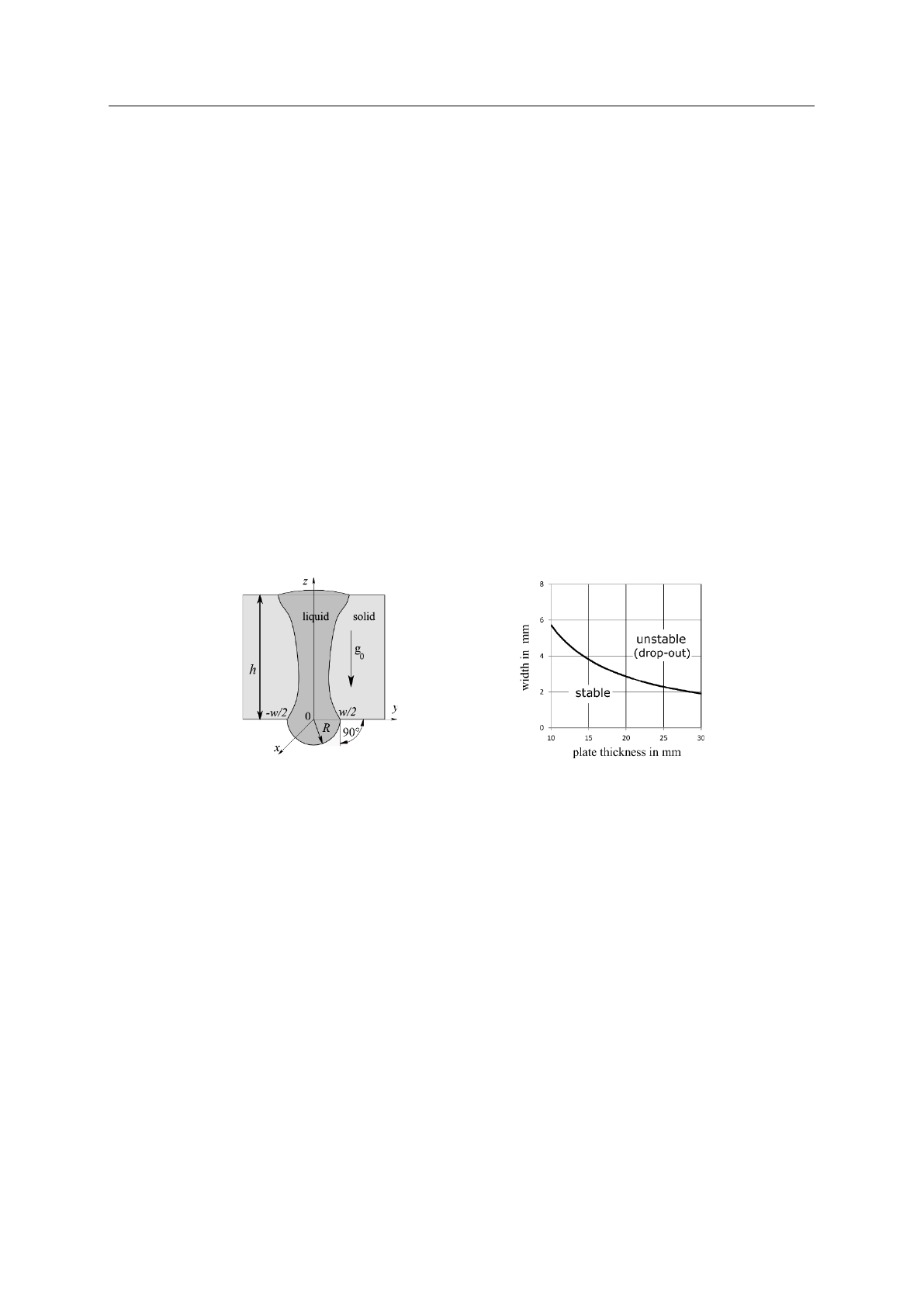
h x w < 2 lcap2, (1)
where h is the plate thickness, w is the root width, lcap = [γ/(ρg0)]1/2 is the capillary length, γ is the surface
tension coefficient, ρ is the density of the melt, and g0 is the gravitational acceleration. The geometrical
sizes on the root side of the weld pool and the stability criterion for liquid steel is shown in Figure 1
according to [9].
Figure 1. Geometrical sizes on the root side of the weld pool (left) stability criterion
for liquid steel (right) [9].
Another typical problem associated with the application of high-power HLAW or wire feed LBW at
deep penetration is the inadequate and non-uniform distribution of filler wire elements over the entire
seam depth which may deteriorate mechanical properties especially in the root part. The high-power
LBW seams are characterized by a high cooling rate, why deteriorated mechanical properties can be
observed, especially at LBW of high-strength steels. So, the use of a filler wire and a homogeneous
mixing of the filler wire plays an integral role to achieve the required mechanical properties. In [10] it
was reported that the Charpy impact toughness of a single-pass hybrid laser-arc welded 25 mm thick
structural steel plate is decreased up to 60 % in the root part (laser-dominated zone) compared to the top
part (arc-dominated zone). Thereby, the decrease in cooling time over depth, the resulting microstructure
and grain size, together with the inhomogeneous mixing have a great impact on the mechanical
properties. Studies dealing with the improvement of the dilution are already known. In [11] the influence
of the arc mode during HLAW on the dilution was studied, where a pulsed or modified spray modes
were recommended. Another effective method to improve the filler wire dilution is to weld thick plates
with a small air gap of 0.3 mm to 0.4 mm as reported in [12,13]. The effectiveness of trailing GMAW
configuration in the mixing of the melt during the welding of 10 mm thick plates was noted in [14]. The
same approach was shown in [15]. Additionally, the shielding gas containing more than 2 % O2 produces
a more homogenous distribution of alloying elements [15]. The impact of the welding parameters such
as laser beam power, wire feed speed and resulting arc power, distance between the two heat sources

18thNordicLaserMaterialsProcessingConference(18thNOLAMP)
IOPConf.Series:MaterialsScienceandEngineering 1135 (2021)012017
IOPPublishing
doi:10.1088/1757-899X/1135/1/012017
3
and the configuration was studied in [16]. It was found that with increasing laser power and arc current,
the filler wire mixing was improved. With a distance of 2 mm to 6 mm between the wire tip extension
and the laser beam, promising results could be achieved.
As the state-of-the-art shows, the challenges during high-power LBW or HLAW of thick-walled
steels, especially the formation of drop-outs and inhomogeneous filler wire mixing is well known.
Methods with the adaptation of the welding parameters for the prevention of an inhomogeneous mixing
were developed for welds with a thickness of up to 15 mm. For thicker plates an additional external
force may be needed to influence the melt flow dynamics for a better mixing behaviour. Therefore,
external magnetic fields were applied in some studies such as in [17-21]. A magnet with a low frequency
in the range of 10 Hz to 20 Hz was applied for the improvement of the element distribution for LBW of
3 mm thick aluminum plate [17-19]. In [20] an external magnetic field was applied for wire-feed LBW
of 10 mm thick austenitic stainless steel to improve the mixing behaviour. It was found that a bulging
region is formed, which narrows the metal transfer channel from the top to the bottom region. A change
of the magnetic field orientation of 10° to 20° to the welding direction was recommended numerically
as well as experimentally to eliminate the bulging phenomenon, thus providing a downward transfer
channel for the melt flow. An approach to prevent sagging and to improve the filler wire mixing at
single-pass HLAW of steel plates with a wall thickness of 20 mm was demonstrated in [21]. Therefore,
an AC magnet was positioned under the workpiece and operated with a frequency of approx. 1.2 kHz.
The goal of this study is to describe the melt flow characteristics in detail and to show the influence
of the magnetic field orientation and oscillation frequency on the filler wire mixing during high-power
LBW and HLAW.
2. Experimental Setup
2.1. Laser beam welding experiments in steel-glass configuration
The high-power fibre laser IPG YLR-20000 with a maximum output power of 20 kW was used as the
laser beam source. The emission wavelength and beam parameter product were 1070 nm and
11 mm x mrad, respectively. The laser radiation was transmitted through an optical fibre with a core
diameter of 200 µm. A laser-processing head BIMO HP has been selected, which provides a
magnification of 2.8 so that the laser beam can be focused into a spot with a diameter of 560 µm. To
detect the keyhole during high-power laser beam welding a special setup was necessary. Welding trials
in butt joint configuration of 25 mm thick structural steel plate (S355J2) and quartz glass were
conducted. A groove with the dimensions of 80 mm x 8 mm x 0.5 mm was milled on the steel plate and
filled with an austenitic powder 316L-Si with Ni as tracing element for the later evaluation. Side views
of the molten pool were taken with help of a highspeed camera Fastcam 1024PCI and interference band-
pass filter at 808 nm and band width of 20 nm. The frame rate and the frame size were 2000 fps and
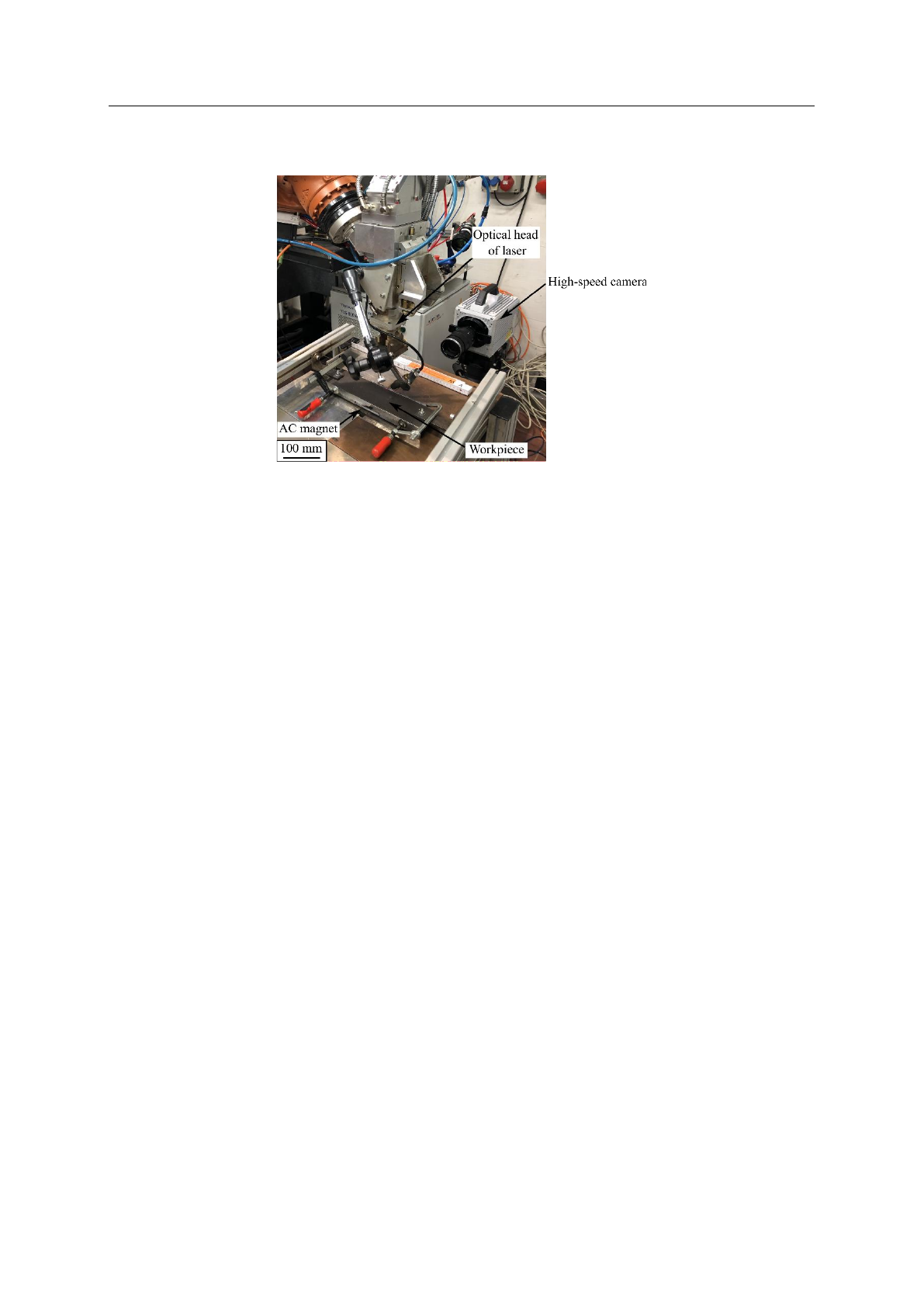
1200 pixels to 1200 pixels, respectively. An oscillating magnetic field generated by an AC
electromagnet was applied to the root side of the weld specimen, where the magnetic field was
perpendicular and induced electric current parallel to the welding direction. The schematic
representation of the experimental setup is shown in Figure 2. The LBW experiments on steel-glass
configuration were performed using a laser beam power of 18.7 kW at a welding speed of 0.9 m min-1
and a focal position of -7 mm. The AC magnet was operated at an oscillation frequency of 1.2 kHz and
a magnet power of 2.1 kW ± 200 W. To protect the arc on the top side from a deflection due to the
oscillating magnetic field, the frequencies have been selected in the kHz range, where the skin layer
depth is less than the plate thickness. For the evaluation of the high-speed recordings the displacements
in the melt-glass interface were estimated and then the velocities were calculated using the optical flow
algorithm according to Lucas-Kanade method.
18thNordicLaserMaterialsProcessingConference(18thNOLAMP)
IOPConf.Series:MaterialsScienceandEngineering 1135 (2021)012017
IOPPublishing
doi:10.1088/1757-899X/1135/1/012017
4
Figure 2. Experimental setup for LBW in steel-glass configuration.
For metallographic inspection, longitudinal sections of the laser beam welded samples were cut.
After polishing and etching the samples using 2 % nital solution, the mixing of the powder over the
thickness was evident.
2.2. Hybrid laser-arc welding experiments
The HLAW experiments were performed using the same laser source as described in Section 2.1.
Additionally, a welding machine Cloos Quineo with a maximum current of 600 A was used as an arc
power source. The laser optics and GMAW torch were mounted on the robot arm, where the laser axis
was positioned 90° to the weld specimen surface and the GMA torch was tilted 25° relative to the laser
axis. The processing head and the magnet remained in a fixed position during the welding, where the
specimens were moved by an external axis. The experiments were carried out on 20 mm thick structural
steel plates (S355J2) in butt joint configuration with an arc leading position and a distance of 4 mm
between the two heat sources and under the following welding parameters: laser beam power of
17.7 kW; welding speed of 1.3 m min- 1; focal position of the laser beam of -5 mm; wire feed speed of
13 m min-1; stick-out of 18 mm; shielding gas mixing consisted of 18% CO2 in Ar with a volume flow
rate of 20 m min-1. A Ni-based solid wire Thermanit625 (ERNiCrMo-3 according to AWS A-5.14) with
a diameter of 1.2 mm was used as a filler wire. Figure 3 shows the setup for the HLAW experiments.
Different magnetic field orientation and oscillating frequencies were tested to determine the influence
of the magnetic parameters on the filler wire mixing.
Loading more pages...