electronics
Article
Washable, Low-Temperature Cured Joints for
Textile-Based Electronics
Jerzy Szalapak 1,*, Vitalij Scenev 2, Daniel Janczak 1, Lukas Werft 2, Sigrid Rotzler 2, Malgorzata Jakubowska 1,
Malte von Krshiwoblozki 3, Christine Kallmayer 3and Martin Schneider-Ramelow 2
Citation: Szalapak, J.; Scenev, V.;
Janczak, D.; Werft, L.; Rotzler, S.;
Jakubowska, M.; von Krshiwoblozki,
M.; Kallmayer, C.; Schneider-Ramelow,
M. Washable, Low-Temperature
Cured Joints for Textile-Based
Electronics. Electronics 2021,10, 2749.
https://doi.org/10.3390/
electronics10222749
Academic Editor: Yuning Li
Received: 16 October 2021
Accepted: 6 November 2021
Published: 10 November 2021
Publisher’s Note: MDPI stays neutral
with regard to jurisdictional claims in
published maps and institutional affil-
iations.
Copyright: © 2021 by the authors.
Licensee MDPI, Basel, Switzerland.
This article is an open access article
distributed under the terms and
conditions of the Creative Commons
Attribution (CC BY) license (https://
creativecommons.org/licenses/by/
4.0/).
1
Faculty of Mechatronics, Warsaw University of Technology, ul. ´sw. A. Boboli 8 p. 145, 02-525 Warsaw, Poland;
Daniel.janczak@pw.edu.pl (D.J.); maljakub@mchtr.pw.edu.pl (M.J.)
2Microperipheric Center, Technical University of Berlin, Gustav-Meyer-Allee 25, 13355 Berlin, Germany;
[email protected] (M.S.-R.)
3Fraunhofer-Institute for Reliability and Microintegration (IZM), System Integration and
Interconnection Technologies, Gustav-Meyer-Allee 25, 13355 Berlin, Germany;
*Correspondence: jerzy.szalapak@pw.edu.pl
Abstract:
Low-temperature die-attaching pastes for wearable electronics are the key components
to realize any type of device where components are additively manufactured by pick and place
techniques. In this paper, the authors describe a simple method to realize stretchable, bendable, die-
attaching pastes based on silver flakes to directly mount resistors and LEDs onto textiles. This paste
can be directly applied onto contact pads placed on textiles by means of screen and stencil printing
and post-processed at low temperatures to achieve the desired electrical and mechanical properties
below 60
◦
C without sintering. Low curing temperatures lead to lower power consumption, which
makes this paste ecological friendly.
Keywords:
conductive adhesive; silver flakes; screen-printing; low temperature; printed electronics
1. Introduction
Electronics and microelectronics play a huge role in people’s lives. Laptops, mobile
phones and smart watches accompany us every day. There is a lot of effort from the scien-
tific and industrial side to further make electronics commensurable with new
shapes [1,2]
and substrates to make it even more functional. One of the main directions of this inte-
gration is textile-integrated electronics (e-textiles, wearables) [
3
]. This type of electronics
must maintain the capabilities of classic electronic systems while meeting new, unusual
requirements, which include flexibility and extensibility [4–6].
E-textiles are already being tested for use in medicine [
7
], sports [
3
] or even for
everyday use [
8
]. One of prospective possibilities to produce textile-integrated electronic
devices are methods from printed electronics, in particular ink-jet [
9
] or screen printing [
10
]
techniques. Using these techniques, it is possible to directly print electronic components
such as electrodes [
11
], sensors [
12
], electrical interconnects, etc. on fabrics or on polymer-
coated fabrics [
13
]. Additionally, the realization of e-textiles by combining the textile and
electronic components with Anisotropic Conductive Film ACF has been reported [
14
].
Washable screen-printed antennas on textiles have been demonstrated in [
15
]. Noteworthy
is the demonstration of ink-jet-printed graphene–silver composite ink on textiles [16].
Finally, washable graphene-based printed electrodes on textiles for wearable health
monitoring devices promise potential applications [
17
]. As the main issues to overcome,
the authors of the above articles mentioned cracking and delamination of the layers. No
washable joints have been reported to date.
Albeit a variety of printed stretchable electronic devices have been reported in the
literature, there are a variety of issues which still remain unsolved [
18
–
20
]. One significant
Electronics 2021,10, 2749. https://doi.org/10.3390/electronics10222749 https://www.mdpi.com/journal/electronics

Electronics 2021,10, 2749 2 of 10
issue is the challenge to maintain stable electrical performance of the textile integrated
device and thereby its components under mechanical deformation. Other important issues
are development techniques that are compatible with conventional textile production
processes, washing durability and the integration of functional electronic devices into
wearable systems [21,22].
In order to shed light into the assembly of electronic components onto textiles, one
needs to emphasize following points. First of all, attached systems should not restrict
motion; however, the main solution, flexible electronic systems with adequate performance,
are still a dream of the future [
23
]. They also require specialized devices for flip-chip
assembly [
24
] and specially prepared contact fields of the chip itself, containing an addi-
tional layer of non-conductive adhesive. Bringing such technology to market will be very
expensive, which may not prove feasible for most companies. For now, the focus should be
on assembling small systems that increase the performance of e-textile systems without any
impact on user comfort in a simple and inexpensive way to implement. However, these
systems must meet the basic requirements for all e-textile systems: they must be flexible,
stretchable and reliable. Additionally, they should work after cleaning, so they should
withstand being put in a washing machine with detergents.
In this work, we developed electrically conductive silver-based pastes for attaching
LEDs and resistors to fabrics. We applied stencil printing [
25
] techniques to print the
paste on textiles. The stencil printing technique was selected because it is an easy to
adapt, industrially proven, a cheap process and it is compatible with the conventional
roll-to-roll [26] processing of textiles.
The authors fabricated low-temperature processible silver-based pastes for die attach-
ment with good electrical stability. Resistors and LEDs were attached onto a 100
×
100 mm
cotton jersey textile and tested electrically before and after multiple washing cycles. Fur-
thermore, the authors conducted mechanical stretching tests up to 1000 cycles and bending
tests up to 10,000 cycles. The electrical contacts were characterized using X-ray microscopy,
Scanning Electron Microscopy (SEM) and Electron X-ray Diffraction Spectroscopy (EDX)
techniques and optical microscopy.
The focus was put on fabricating a paste for attaching the resistors and LEDs at
lower temperatures, below 60
◦
C, to avoid the degradation of textile substrates. To our
knowledge, no comparable pastes for die attaching have been reported to date.
2. Materials and Methods
2.1. Thermal Transfer Contact Pad Preparations
The silver contact pads were made by transfer screen printing methods. Thermal
transfer printing is a type of transfer printing commonly used in the textile industry to
apply layers to textile substrates. This indirect printing technique uses plastisol inks and
special substrates in the form of foil or transfer papers. It allows the application of a
mirror image of a multi-layer pattern previously printed on a temporary substrate [
23
]
onto a textile substrate. Authors in earlier works developed a polymer resin based on
thermoplastic polyurethane (TPU) and used it to develop a silver composition with a high
mechanical tensile strength [8].
As the functional phase, to develop a high conductive composite, silver flakes AX
20 LC
from Amepox Company (Łód´z, Poland) with average particle sizes of 2–4
µ
m were
used. A printable composition containing 75 wt.% silver flakes in 15 wt.% solution of TPU
in dimethylformamide (DMF) was applied through the 77 T screen. After curing at 130
◦
C
for 15 min, a layer of plastisol glue was applied to the silver layer, and then the contacts
were deposited onto a textile substrate using the thermal transfer method. The process was
conducted in an air atmosphere.
2.2. Joining Material Application
The pastes designed for joining were applied with screen printing, stencil printing and
with a needle dispenser. To join LEDs and resistors, die attach pastes were fabricated as
Electronics 2021,10, 2749 3 of 10
described as follows: silver flakes of two different types, AA-4077 (PSD90 of
15.6 µm
)
and AC-6652 (PSD90 of 1.7
µ
m), were supplied by Metalor Technologies SA (Marin,
Switzerland). Fugitive rheology additive and dispersing agent, 3,5-Dimethyl-1-hexin-
3-ol, DBE-9 (Dibasic Esters) were purchased from Sigma Aldrich(St. Louis, MI, USA).
Polymer slurry Noriphan and solvent-based additive F013 were purchased from Proell
GmbH (Weißenburg, Bayern, Germany). The silver flakes were added to the slurry at a
concentration of 50% to 80%, where the relative amount of each silver flake type compared
to entire amount of silver in the formulation was 75% of AC-4077 and 25% of AA-6652. The
ratio of 1:3 was chosen based on our previous work [
27
] and the study published in [
28
].
Subsequently, after adding the silver flakes to the Noriphan, the slurry of DBE-9 was added,
and in the following step 3,5-Dimethyl-1-hexin-3-ol and subsequently Solvent F013 (Proell
GmbH, Weißenburg, Bayern, Germany) were added. The entire formulation was speed
mixed at 800 rpm for one minute at room temperature. Note that the paste formulations
were labelled VJ 50, VJ 60, VJ 70 and VJ 80 corresponding to the concentration of silver
particles in the formulations of 50%, 60%, 70% and 80%, respectively.
VJ pastes’ dynamic viscosity was tested using the Brookfield RS CPS+ cone-plate
rheometer. The pastes containing 50, 60, 70 and 80% of the functional phase remain within
the range of 10–30 Pa
·
s, implicating that the designed pastes are suitable for screen and
stencil printing.
For current measurements, VJ pastes were applied with a needle dispenser onto the
contact pads prepared earlier on the cotton substrates. SMD 0805, 0
Ω
resistors as well as
0603 LEDs were joined onto the contact pads with previously applied pastes and cured for
30 min at 50
◦
C. Next, a drop of TPU for encapsulation was applied with a needle dispenser
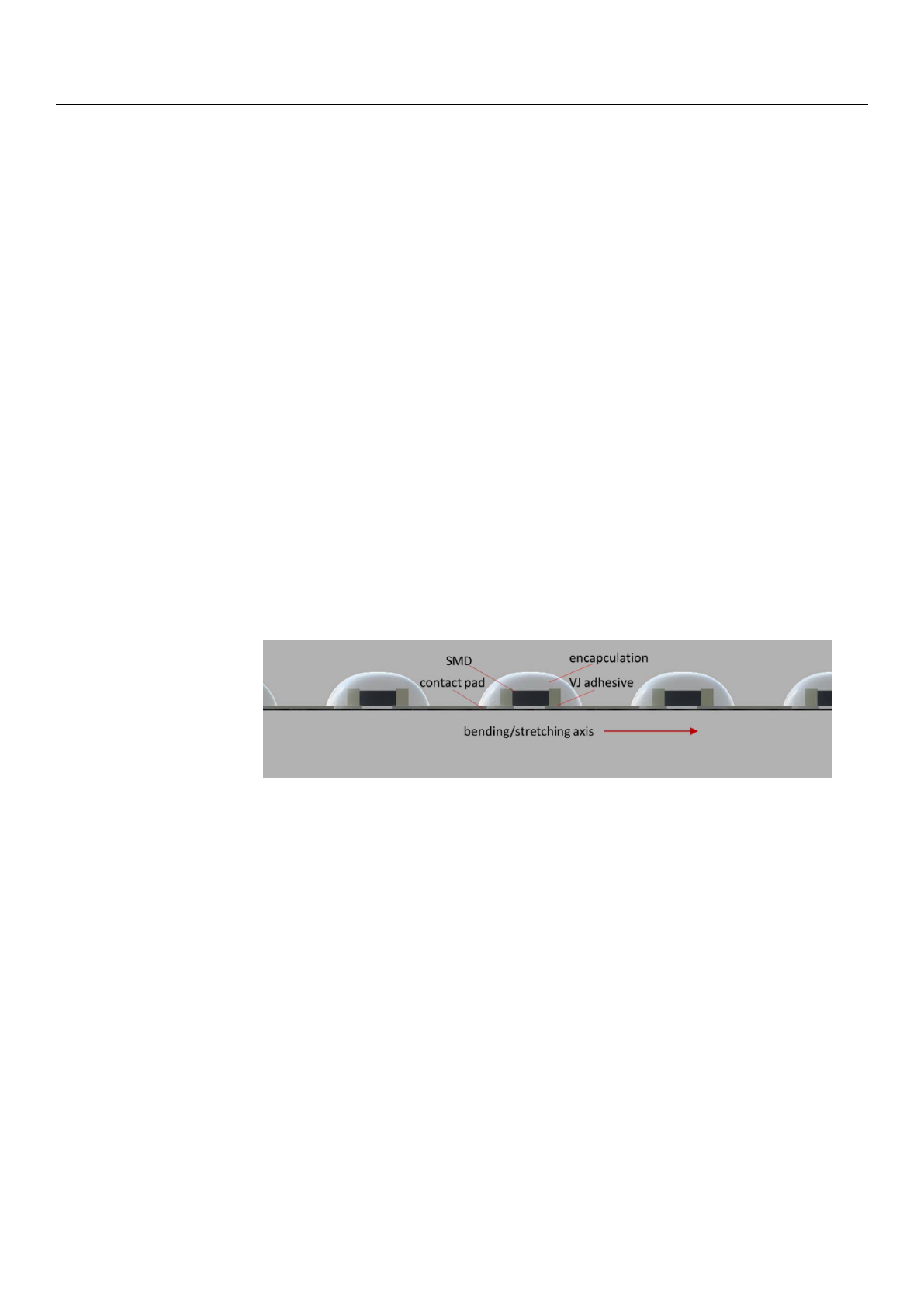
and cured for another 30 min. Schematic is shown in Figure 1.
Electronics 2021, 10, 2749 3 of 10
2.2. Joining Material Application
The pastes designed for joining were applied with screen printing, stencil printing
and with a needle dispenser. To join LEDs and resistors, die attach pastes were fabricated
as described as follows: silver flakes of two different types, AA-4077 (PSD90 of 15.6 µm)
and AC-6652 (PSD90 of 1.7 µm), were supplied by Metalor Technologies SA (Marin, Swit-
zerland). Fugitive rheology additive and dispersing agent, 3,5-Dimethyl-1-hexin-3-ol,
DBE-9 (Dibasic Esters) were purchased from Sigma Aldrich(St. Louis, MI, USA). Polymer
slurry Noriphan and solvent-based additive F013 were purchased from Proell GmbH
(Weißenburg, Bayern, Germany). The silver flakes were added to the slurry at a concen-
tration of 50% to 80%, where the relative amount of each silver flake type compared to
entire amount of silver in the formulation was 75% of AC-4077 and 25% of AA-6652. The
ratio of 1:3 was chosen based on our previous work [27] and the study published in [28].
Subsequently, after adding the silver flakes to the Noriphan, the slurry of DBE-9 was
added, and in the following step 3,5-Dimethyl-1-hexin-3-ol and subsequently Solvent
F013 (Proell GmbH, Weißenburg, Bayern, Germany) were added. The entire formulation
was speed mixed at 800 rpm for one minute at room temperature. Note that the paste
formulations were labelled VJ 50, VJ 60, VJ 70 and VJ 80 corresponding to the concentra-
tion of silver particles in the formulations of 50%, 60%, 70% and 80%, respectively.
VJ pastes’ dynamic viscosity was tested using the Brookfield RS CPS+ cone-plate rhe-
ometer. The pastes containing 50, 60, 70 and 80% of the functional phase remain within
the range of 10–30 Pa∙s, implicating that the designed pastes are suitable for screen and
stencil printing.
For current measurements, VJ pastes were applied with a needle dispenser onto the
contact pads prepared earlier on the cotton substrates. SMD 0805, 0 Ω resistors as well as
0603 LEDs were joined onto the contact pads with previously applied pastes and cured
for 30 min at 50 °C. Next, a drop of TPU for encapsulation was applied with a needle
dispenser and cured for another 30 min. Schematic is shown in Figure 1.
Figure 1. Schematic of diodes/resistors mounted on textile substrate.
2.3. Electrical Measurements
Resistivity was calculated on the basis of measured sheet resistance of layers printed
on polycarbonate layers. The final resistivity after 30 min curing at 50 °C for VJ 60 was 1.3
× 10−6 Ωm, 1.0 × 10⁻⁶ Ωm for VJ 70 and 6 × 10⁻⁷ Ωm for VJ 80. What is worth mentioning,
after 30 min curing at 90 °C, VJ 70 resistivity drops to 7.2 × 10⁻⁷ Ωm. Joint resistivity may
differ from layer resistivity. That is why we decided to focus on joint resistance and its
change after mechanical tests.
The samples for electrical, bending and stretching measurements were prepared on
cotton substrates with contact pads. Chains of five resistors in line were attached to the
contact pads. Prior to mechanical measurements, all of the samples were electrically meas-
ured using a Keithley 2001 multimeter. Additionally, LED chains were made in the same
manner as resistors.
2.4. Mechanical Shear Strength Measurements
Measurements of the shear-strength resistance of joints were made on a two-column
Comtech testing machine with a 500 N sensor, where the shear clamp is attached to a
Figure 1. Schematic of diodes/resistors mounted on textile substrate.
2.3. Electrical Measurements
Resistivity was calculated on the basis of measured sheet resistance of layers printed
on polycarbonate layers. The final resistivity after 30 min curing at 50
◦
C for VJ 60 was
1.3 ×10⁻⁶Ωm,
1.0
×
10
−6Ω
m for VJ 70 and 6
×
10
−7Ω
m for VJ 80. What is worth
mentioning, after 30 min curing at 90
◦
C, VJ 70 resistivity drops to 7.2
×
10
−7Ω
m. Joint
resistivity may differ from layer resistivity. That is why we decided to focus on joint
resistance and its change after mechanical tests.
The samples for electrical, bending and stretching measurements were prepared on
cotton substrates with contact pads. Chains of five resistors in line were attached to the
contact pads. Prior to mechanical measurements, all of the samples were electrically
measured using a Keithley 2001 multimeter. Additionally, LED chains were made in the
same manner as resistors.
2.4. Mechanical Shear Strength Measurements
Measurements of the shear-strength resistance of joints were made on a two-column
Comtech testing machine with a 500 N sensor, where the shear clamp is attached to a strain
gauge, and the force at which shearing takes place is recorded on a computer. The accuracy
was ±0.1 N.
Substrates and dummy dies were prepared using 1 mm-thick polycarbonate. Sub-
strates were 10
×
10 mm and dummy dies were 2
×
2 mm. Prior to joining, surfaces were

Electronics 2021,10, 2749 4 of 10
cleaned with acetone, then contact pads were stencil-printed, with layer thicknesses at
40 µm
prior to attaching the dummy dies. Curing was conducted with the same parameters
as for the cotton samples: 30 min curing at 50
◦
C for pastes and an additional 30 min of
curing at 50 ◦C for samples with additional TPU encapsulation.
2.5. Stretching and Bending Tests
Stretching and bending tests were conducted with a Comtech testing machine as
well. Cotton samples with encapsulated 0
Ω
resistors and diodes were used. A total of
1000 stretching
cycles of the textile samples were carried out along the mounted elements
with a speed of 30 cycles/min and a final elongation of 110%. Electrical measurement of
the resistor chains was conducted after 100, 300, 500 and 1000 cycles. Diodes were tested
both one by one and all at the same time.
To test the bending reliability, 10,000 cycles were conducted, with the radius changing
from
∞
to 5 mm and a speed of 60 cycles/minute. Electrical measurements were conducted
after 1000, 3000, 5000 and 10,000 cycles.
2.6. Washing Machine Tests
To perform the washing machine test, 8 samples fixed onto double-layered plain
woven cotton swatches (200
×
200 mm) were prepared. Each sample contained five
0603 SMD diodes mounted with VJ 60 and five diodes mounted with VJ 70, all of them
encapsulated. Four such samples were put into a protective washing bag, typical for
washing delicate laundry items. The other four samples were put directly in the machine.
The washing machine used for the tests was an Electrolux WH645, an ISO 6330-
compliant machine (type A in the standard). The washing program was compiled using
Electrolux Laundry Program Manager LPM 6. It is modeled after a household washing
program for silk/delicates. The structure of the program is:
-
main washing phase—25 min, 40% on-time (percentage of time when the drum is
turning), water volume: 12 L,
- intermediate spinning (2 min, 500 rpm),
- 2×rinsing (cold water, 40% on-time, 12 L),
- final spinning (5 min, 800 rpm).
The washing temperature during the main washing phase was 30
◦
C, with a total
program duration of around 40 min (+/
−
2 min). Samples were air dried overnight. The
detergent used for the tests was Frosch liquid wool detergent (40 mL). For a total load of
2 kg, polyester-based load items were added to the samples, in accordance with ISO 6330.
3. Results
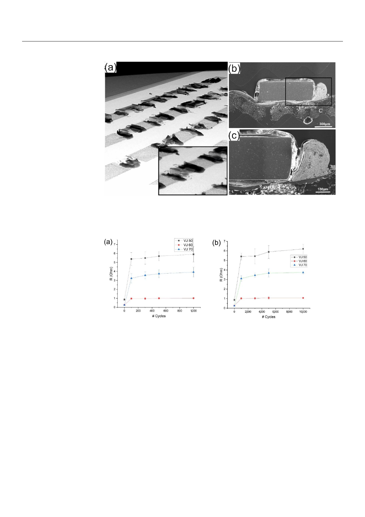
Figure 2a depicts X-ray microscope images of joined resistor elements on textile. Fur-
thermore, an SEM image of the cross-section of a resistor element joined with a
VJ 60
paste
(Figure 2b) with the corresponding EDS material composition map (Figure 2c)
is presented.
The electrical resistance after mechanical stretching and bending measurements is
shown in Figure 3a,b. Resistor chain resistance after mounting was the lowest for VJ 60,
containing 60% of silver particles and significantly higher for VJ 70 and VJ 50 containing
70% and 50% of silver particles. In the case of stretching (Figure 3a), the largest increase in
resistance after 1000 cycles was measured for VJ 70 with 26%, from 3.11
Ω
to 3.92
Ω
. For
VJ 60, the resistance changed from 0.95 Ωup to 1.01 Ω, which is an increase of about 6%.
Electronics 2021,10, 2749 5 of 10
Electronics 2021, 10, 2749 5 of 10
Figure 2. X-ray micrographs of resistors picked and placed on textile (a), SEM-micrographs of the
cross-section of a resistor on textile (b). Zoom-in of the black framed region in (b) of the contact area
resistor textile (c).
The electrical resistance after mechanical stretching and bending measurements is
shown in Figure 3a,b. Resistor chain resistance after mounting was the lowest for VJ 60,
containing 60% of silver particles and significantly higher for VJ 70 and VJ 50 containing
70% and 50% of silver particles. In the case of stretching (Figure 3a), the largest increase
in resistance after 1000 cycles was measured for VJ 70 with 26%, from 3.11 Ω to 3.92 Ω. For
VJ 60, the resistance changed from 0.95 Ω up to 1.01 Ω, which is an increase of about 6%.
Figure 3. Dependence of the electrical resistance of resistors chain on (a) number of stretching and
(b) bending cycles.
For the bending tests, the biggest change was an increase of 20% for both VJ 50 and
VJ 70 after 10,000 cycles. For the best conducting VJ 60, the resistance rose by 14%. It is
worth mentioning that none of tested samples stopped working during the cycle testing.
Additionally, samples with attached LEDs were tested and none of them stopped work-
ing.
When looking at the shear strength of joints prepared with the VJ pastes, the smaller
the silver content of the paste, the higher the shear strength, as shown in Figure 4. The
highest shear strength without encapsulation, 3.7 MPa, was observed for VJ 60, while VJ
50 had 3.4 MPa. Joints created with pastes containing more silver particles had signifi-
Figure 2.
X-ray micrographs of resistors picked and placed on textile (
a
), SEM-micrographs of the
cross-section of a resistor on textile (
b
). Zoom-in of the black framed region in (
b
) of the contact area
resistor textile (c).
Electronics 2021, 10, 2749 5 of 10
Figure 2. X-ray micrographs of resistors picked and placed on textile (a), SEM-micrographs of the
cross-section of a resistor on textile (b). Zoom-in of the black framed region in (b) of the contact area
resistor textile (c).
The electrical resistance after mechanical stretching and bending measurements is
shown in Figure 3a,b. Resistor chain resistance after mounting was the lowest for VJ 60,
containing 60% of silver particles and significantly higher for VJ 70 and VJ 50 containing
70% and 50% of silver particles. In the case of stretching (Figure 3a), the largest increase
in resistance after 1000 cycles was measured for VJ 70 with 26%, from 3.11 Ω to 3.92 Ω. For
VJ 60, the resistance changed from 0.95 Ω up to 1.01 Ω, which is an increase of about 6%.
Figure 3. Dependence of the electrical resistance of resistors chain on (a) number of stretching and
(b) bending cycles.
For the bending tests, the biggest change was an increase of 20% for both VJ 50 and
VJ 70 after 10,000 cycles. For the best conducting VJ 60, the resistance rose by 14%. It is
worth mentioning that none of tested samples stopped working during the cycle testing.
Additionally, samples with attached LEDs were tested and none of them stopped work-
ing.
When looking at the shear strength of joints prepared with the VJ pastes, the smaller
the silver content of the paste, the higher the shear strength, as shown in Figure 4. The
highest shear strength without encapsulation, 3.7 MPa, was observed for VJ 60, while VJ
50 had 3.4 MPa. Joints created with pastes containing more silver particles had signifi-
Figure 3.
Dependence of the electrical resistance of resistors chain on (
a
) number of stretching and
(b) bending cycles.
For the bending tests, the biggest change was an increase of 20% for both VJ 50 and
VJ 70 after 10,000 cycles. For the best conducting VJ 60, the resistance rose by 14%. It is
worth mentioning that none of tested samples stopped working during the cycle testing.
Additionally, samples with attached LEDs were tested and none of them stopped working.
When looking at the shear strength of joints prepared with the VJ pastes, the smaller
the silver content of the paste, the higher the shear strength, as shown in Figure 4. The
highest shear strength without encapsulation, 3.7 MPa, was observed for VJ 60, while VJ 50
had 3.4 MPa. Joints created with pastes containing more silver particles had significantly
lower mechanical parameters. For comparison, a commercial conductive epoxy adhesive,
labeled as CH (Figure 4), was used, with joints cured at the recommended 65
◦
C for 20 min.
According to the data sheet, the shear strength should be 6.5 MPa, while the measurements
were allowed to achieve 4.1 MPa, 10% higher than VJ 60. It should be noted that the
commercial conductive epoxy’s resistivity shown in the data sheet is an order of magnitude
worse compared to the VJ pastes created by the authors.
Loading more pages...