
FACTA UNIVERSITATIS
Series: Mechanical Engineering Vol. 19, No 4, 2021, pp. 613 - 632
https://doi.org/10.22190/FUME210106020K
© 2021 by University of Niš, Serbia | Creative Commons License: CC BY-NC-ND
Original scientific paper
ON THE INFLUENCE OF MULTIPLE EQUILIBRIUM
POSITIONS ON BRAKE NOISE
Sebastian Koch, Emil Köppen, Nils Gräbner, Utz von Wagner
Chair of Mechatronics and Machine Dynamics, Technische Universität Berlin, Germany
Abstract. Brake noise, especially brake squeal, has been a subject of intensive research
both in industry and academia for several decades. Nevertheless, the state of the art
simulations does not provide a predictive tool, and extensive experimental investigations
are still necessary to find an appropriate design. Actual investigations focus on the
consideration of nonlinearities which are in fact essential for this phenomenon.
Unfortunately, by far not all relevant effects caused by nonlinearities are known. One of
these nonlinear effects that the actual research focuses on is the limit cycle behavior
representing squeal. In contrast to this, the actual paper considers the influence of the
equilibrium position established while applying the brake pressure. The elements of the
brake, namely, the carrier, caliper and pad, are highly nonlinear and elastically coupled
and allow for multiple equilibrium positions depending e.g. on the initial conditions and
transient application of the brake pressure while the frictional contact between the pads
and the disk may excite small amplitude self-excited vibrations around this equilibrium,
i.e. squeal. The current paper establishes a method and corresponding setup, to measure
the position engaged by the brake components using an optical 3D-measuring system.
Subsequently, it is demonstrated that in fact different equilibrium positions can be
engaged for the same operation parameters and that the engaged position can be decisive
for the occurrence of squeal. In fact, certain positions result in squeal while others do
not for the same operation parameters. Taking this effect into consideration may have
significant consequences for the design of brakes as well as simulation and experimental
investigation of brake squeal.
Key Words: Brake Noise, Nonlinearities, Equilibrium Positions, Digital Image
Correlation
Received January 06, 2021 / Accepted February 15, 2021
Corresponding author: Sebastian Koch
Chair of Mechatronics and Machine Dynamics, Technische Universität Berlin, Einsteinufer 5, 10587 Berlin
E-mail: koch@tu-berlin.de

614 S. KOCH, E. KÖPPEN, N. GRÄBNER, U.V. WAGNER
1. INTRODUCTION
Brake squeal and other brake noises are typical examples for NVH (Noise, Vibration,
Harshness) problems in the automotive industry. These phenomena in general do not represent
safety risks but are merely comfort issues. Their avoidance nevertheless requires a considerable
amount of development and testing, making brake noise a topic of numerous scientific and
technical publications. Several review papers, e.g. [1] and [2], provide overviews on the topic.
The brake squeal simulation is still a tool with only a limited predictive character which
almost always requires, in addition, experimental investigations. It is well known that the
alteration of operating parameters such as brake pressure, brake torque, speed or brake disk
temperature during such experiments has a strong influence on the squealing behavior, see e.g.
[3]. Therefore, the necessary number of tests to classify the brake in such manner is extensive,
e.g. [4]. The situation becomes more complicated by the fact that there is a possibility for
squealing to sometimes occur and sometimes not even during the tests with the identical
operation parameters [5-7]. Ref. [6] mainly considers thereby changes in the direction in which
the brake components obviously capture significantly different positions as well as the
corresponding influence on the squealing behavior.
The state of the art procedure to experimentally classify the squealing behavior of the
passenger car brakes is SAE J2521. During this test, the entire brake and the wheel
suspension are mounted on a dynamo test bench. A huge amount of braking operations is
performed on different parameters, while the noise level is recorded to categorize whether
the brake is squealing or not.
On the other hand, the industrial state of the art for the brake squeal simulation is based
on the consideration of simulation data gathered from Finite Element (FE) models. The
analysis is divided into multiple steps [8]. In the first step, the brake pressure is applied
quasi statically to determine the equilibrium position and the contact forces. Therefore, a
nonlinear contact analysis is used. Then the model is linearized with respect to the found
equilibrium position. Obviously, the equations of motion of this linearized model depend
on this equilibrium position. The linear model is finally used for a complex eigenvalue
analysis (CEA). Since these models contain, if correctly set up, the mechanism of self-
excitation due to the friction forces between the disk and the pad, there is a possibility of
instability of the equilibrium position and the mode shapes with eigenvalues with a positive
real part are considered as modes potentially associated with squealing [9]. However, linear
instability does not represent the observed behavior of a squealing brake, as unstable
solutions in linear models show an increasing amplitude above all boundaries with time
while the real brake squealing is represented by a more or less stationary behavior with
distinct frequencies and finite amplitudes. Therefore, the behavior observed in the brake
squealing can only be represented by nonlinear models [10]. Hereby, nonlinearities limit
the increasing vibration caused by the self-excitation finally ending in a limit cycle [10,
11]. Several attempts have been made in the past years to describe these effects and to
investigate the resulting effects, e.g. [12-19]. These attempts are essential for several
reasons. One reason is that the nonlinearity limiting the limit cycle could be a key for
avoiding squealing, i.e. if this nonlinearity could be designed in a way that the amplitudes
of the limit cycles are irrelevant for noise, the problem of brake squeal would be solved.
Another reason is that nonlinearities can play a key role, when it comes to the desired
predictive character of the simulation methods. In [11] it is shown that the mode shape
belonging to the largest positive eigenvalue real part is not necessarily the one occurring

On the Influence of Multiple Equilibrium Positions on Brake Noise 615
in the limit cycle, as nonlinearities may limit that mode much earlier than another mode
shape with a smaller positive real part.
As a conclusion, nonlinearities are essential for the description of brake squeal and may
play a key role for its suppression. Nevertheless, as the description above makes obvious,
nonlinearities, if actually considered, are so far considered in detail only at one place of the
simulation process, namely in limiting the increasing vibrations. Another obvious point,
where nonlinearities play a role, is in determining the equilibrium position. Here, in general,
only one equilibrium position and its dependency on parameters such as brake pressure are
considered, while the immanent nonlinearities could also result in multiple equilibrium
positions with the same parameters due to different initial conditions. This fact is completely
ignored in state of the art simulations. Most people having done experiments with squealing
brakes may have experienced that a squealing brake can be brought to silence or vice versa,
if the positions of some parts of the brake are manipulated e.g. by pressing temporarily a
screwdriver on them. Sometimes it is visible with the naked eye that the position of the brake
parts is not the same after this manipulation as it was before, so that a new equilibrium
position has been reached, possibly with decisive influence on the noise behavior.
For both types of above mentioned influences of nonlinearities, the initial conditions
play an essential role in determining which solution appears. With respect to the limit cycle,
the initial conditions decide in the case of coexistent stable limit cycle and stable trivial
solution about the appearance of squealing [20], but the same happens, if different
equilibrium positions are possible due to nonlinearities, where the stability behaviors may
differ from each other. In reality, nonlinearities affect the noise behavior in both cases and
the dependence on the initial conditions is the explanation why brake squeal sometimes
occurs and sometimes not for the same operation conditions.
The present paper aims to investigate experimentally the influence of the actually
engaged equilibrium position on the noise behavior and, therefore, to investigate another
influence of nonlinearities on the brake squeal. In reality, the engaged equilibrium position
is determined during the process of applying the brake pressure. This process is highly non-
linear especially due to the new contacts occurring therein. Therefore, it is highly probable
that different equilibrium positions can be established depending on the initial conditions,
respectively the state of the brake before the brake pressure is applied. Additionally, there
might be some influence of external excitation on the engaged equilibrium position.
As experiments show, the concept of one engaged stationary equilibrium position is an
idealization in simulations, as these equilibrium positions may also change periodically
during the turning of the disk due to disk wobbling or other imperfections. Nevertheless,
the following investigations show that there is significant dependence of the occurrence of
squealing on the (medium) absolute and relative positions of the brake parts; they also show
that significant different positions are possible even for constant operation parameters.
In the metrological investigation it is necessary to consider that the changes in the
positions are slow (quasi static) and with respect to the displacement in the order of
0.1 millimeters or more. Squealing, however, has usually a much smaller displacement
amplitude (µm range or smaller) and it occurs at frequencies in the range of approximately
1 to 16 kHz. While conventional set-ups regarding the investigation of brake squeal are
focused on measuring these high frequency vibrations by using accelerometers or laser
vibrometers, other methods must be established for measuring the equilibrium positions.
616 S. KOCH, E. KÖPPEN, N. GRÄBNER, U.V. WAGNER
The paper is structured as follows. First, the developed test bench is presented. The test
setup comprises an optical 3D measuring system filming the brake. The position data of
respective parts can be determined using digital image correlation (DIC). This method
allows the determination of the position of many points on the structure for low frequencies
(quasi static) and comparatively large displacements. Based on this, two test series are
presented. Test series number one is used to investigate whether changes in equilibrium
position can occur under almost identical parameters for braking torque, speed and temperature
and whether these changes have a significant influence on the squealing behavior. In a second
test series, what is investigated is the extent to which an increasing braking torque influences
the equilibrium position. The results are collected and discussed in a manner which illustrates
the essential influence of the equilibrium position on the squealing behavior.
2. EXPERIMENTAL SETUP
The main task of the experimental setup is to detect differences in the equilibrium
position of the examined floating caliper disk brake while the disk is rotating at a specific
speed and a specific brake pressure is applied. Especially the brake components carrier,
caliper and pad are considered. Furthermore, the test bench must be able to detect squealing
events and to record the corresponding parameters, namely rotational speed, brake torque,
respectively, brake pressure and temperature.
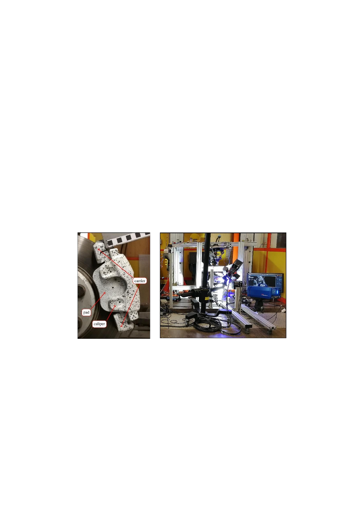
Fig. 1 Left: main components, i.e. the carrier, caliper and pad of the investigated industrial
floating caliper brake [21]. Right: overview of the test bench with mounted brake
and optical 3D measuring system [22]
Fig. 1 shows one of the brake test benches at MMD TU Berlin, which was already used
in several prior works, e.g. [11]. It includes an industrial floating caliper disk brake driven
by an electric motor via the original drive shaft from the inner side. To allow for a wider
range of equilibrium positions, the clamp connecting the carrier and the caliper
(Fig. 16 left) in the serial setup was omitted in these two first test series. Nevertheless,
On the Influence of Multiple Equilibrium Positions on Brake Noise 617
similar effects are also observed when the clamp is mounted, as demonstrated in a third
test series. The entire control of the brake pressure and rotational speed is done manually.
Compared to industrial test benches this set up does not allow the investigation of high
rotational speeds or high torques and, therefore, it is not capable of analyzing the brake
performance. Nevertheless, brake squeal generally requires only low rotational speeds and
torques. The main advantage of this set-up is that most parts of the brake are perfectly
accessible for optical measurements. Here, this accessibility is used to observe one side of
the brake using a GOM Aramis optical 3D measuring system, determining the position of
the brake parts with a high spatial resolution.
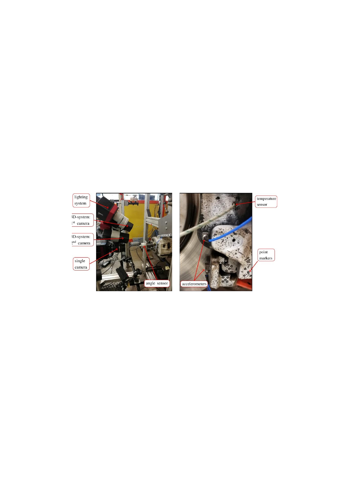
This 3D measuring system essentially consists of two cameras and a lighting system. It
enables the capturing of grayscale images with 25 frames per second (fps) and a resolution
of 2752 by 2200 pixel. Self-adhesive point markers with an inner diameter of 1.5 mm are
attached to the components carrier, pad and caliper (see Fig. 2 right). The image sequence
recorded by the 3D-system makes it possible to determine the spatial movement of these
point markers by using DIC for homologous point tracking in all three dimensions. The
equipment used is state of the art.
Fig. 2 Details of the test bench [23]. Left: 3D-system, single camera, angle sensor and
mounting for the coordinate system. Right: accelerometers, temperature sensor and
point markers
Nevertheless, the computation algorithm as described in [24] for the determination of
displacement data shall be briefly sketched. The glued-on point markers are identified and
tracked via image recognition techniques. The center of the point determines the position
of the measurement point. Therefore, the tracking resolution is in subpixel accuracy and
for this setup in the order of approximately 5µm [25, 26]. The subpixel resolution is possible
since the points consist of several pixels and, therefore, the center can be interpolated. Each
camera records a separate image sequence, and the point tracking is also done separately.
According to [27] the data from both cameras can be combined to determine the 3D
position of the point markers.
Loading more pages...