
JOURNAL OF LIGHTWAVE TECHNOLOGY, VOL. 40, NO. 7, APRIL 1, 2022 2045
Wavelength Locking and Determination in Tunable
Lasers by Gain Voltage Measurement
Magnus Happach , David de Felipe , Victor Nicolai Friedhoff, Martin Kresse, Gelani Irmscher, Moritz Kleinert ,
Crispin Zawadzki, Walter Brinker, Martin Möhrle, Norbert Keil , Werner Hofmann , Member, IEEE,
and Martin Schell
Abstract—In this paper we demonstrate the feasibility of low-cost
lasers with an integrated wavelength locker and wavelength meter.
We use a reflection at the polymer chip to single mode fiber butt
coupling point to establish optical feedback outside the laser cavity
to make the gain voltage wavelength dependent. With this signal we
can keep the alignment of the lasing mode and the Bragg grating
optimal and can determine the absolute wavelength of the emitted
wavelength without additional hardware.
Index Terms—Aliasing, continuous tuning, gain voltage,
optical feedback, optical feedback interferometry, tunable laser,
wavelength locking, wavelength-meter.
I. INTRODUCTION
THE number of devices connected to IP networks will
extend 28.5 billion devices by 2022 [1]. In order to meet
the high demand for bandwidth optical access networks such
as the wavelength division multiplexing passive optical net-
work (WDM-PON) are being used. One additional approach
are digital super-mode distributed Bragg reflectors (DBR) in a
WDM-PON with a central optical line terminal (OLT) [1], [2],
[3]. Signals from several optical network units (ONU) are multi-
plexed by an arrayed-waveguide-grating (AWG) and transmitted
over 40 km to the OLT. The channel selection to the correct
ITU grid of each ONU is achieved by the wavelength filtering
of the AWG. During the initialization phase, the laser of the
Manuscript received July 25, 2021; revised October 23, 2021; accepted
November 26, 2021. Date of publication November 30, 2021; date of current
version April 4, 2022. (Corresponding author: David de Felipe.)
Magnus Happach was with the Fraunhofer Heinrich Hertz Institute, 10587
Berlin, Germany. He is now with Sonova AG, 8712 Stäfa, Switzerland.
David de Felipe, Martin Kresse, Gelani Irmscher, Moritz Kleinert, Crispin
Zawadzki, Walter Brinker, Martin Möhrle, and Norbert Keil are with the
Fraunhofer Heinrich Hertz Institute, 10587 Berlin, Germany (e-mail: david.
fraunhofer.de; [email protected].de).
Victor Nicolai Friedhoff is with the Humboldt University of Berlin, 10117
Werner Hofmann is with the Institute for Solid State Physics,
Technical University of Berlin, 10623 Berlin, Germany (e-mail:
werner[email protected]).
Martin Schell is with the Fraunhofer Heinrich Hertz Institute, 10587 Berlin,
Germany, and also with the Institute for Solid State Physics, Technical University
Color versions of one or more figures in this article are available at
https://doi.org/10.1109/JLT.2021.3131410.
Digital Object Identifier 10.1109/JLT.2021.3131410
ONU tunes the wavelength while the OLT reports the received
power level via the feedback link. Once the tuning settings for
maximum transmission power of the channel have been found,
further wavelength stability is kept by a centralized wavelength
locker [4] at the OLT. Another reason for using centralized multi-
wavelength lockers for WDM systems are low cost. Components
for multi-wavelength lockers include a beam-splitter, an etalon
for wavelength filtering a photodiode for the filtered signal, and
a second photodiode for power monitoring [5].
Even though this approach has turned out to be practicable,
it has been developed with a view to achieving the lowest costs
of the individual ONUs. Equipping each unit with a wavelength
meter as well as a wavelength locker is cost-intensive. To release
some financial pressure from the network’s design, we will focus
in this paper on an improved ONU design, aiming for a laser
that allows the wavelength to be individually determined and
stabilized without the feedback from the OLT.
Although the functionality of wavelength lockers on chip
level for laser applications has been demonstrated [6] by the
integration of on-chip free beam optics [7], the cost factor of
the components and the optimization of the assembly process
have not been pushed far enough yet. It then stands to reason
that one should try to reduce the optical components and switch
to a purely eclectic measurement.
One fully electrical wavelength locking scheme has been
demonstrated by [8] which uses the gain voltage as a tem-
perature sensor. A frequency generator sinusoidally modulates
the current at the gain section and enables the measuring the
series resistance of the diode via a lock-in amplifier. Resistance
variations indicate temperature changes and can be used to feed
a control loop to adjust the current of the thermo-electric cooler.
With this technique, temperature changes of 20-55 °C in the
environment can be attenuated and the frequency deviations
were reduced to ±1 GHz. However, this approach requires
a cooled laser module and additional electrical components,
increasing overall costs.
However, further investigations [9], [10], [11] show that the
gain voltage can be a wavelength dependent parameter, without
any additional equipment but a small reflection outside the laser
cavity, which reintroduces parts of the emitted beam back into
the laser cavity. This integrated optical feedback makes the gain
voltage wavelength dependent and can be used as monitor signal
for wavelength locking and wavelength determination.
This work is licensed under a Creative Commons Attribution 4.0 License. For more information, see https://creativecommons.org/licenses/by/4.0/
2046 JOURNAL OF LIGHTWAVE TECHNOLOGY, VOL. 40, NO. 7, APRIL 1, 2022
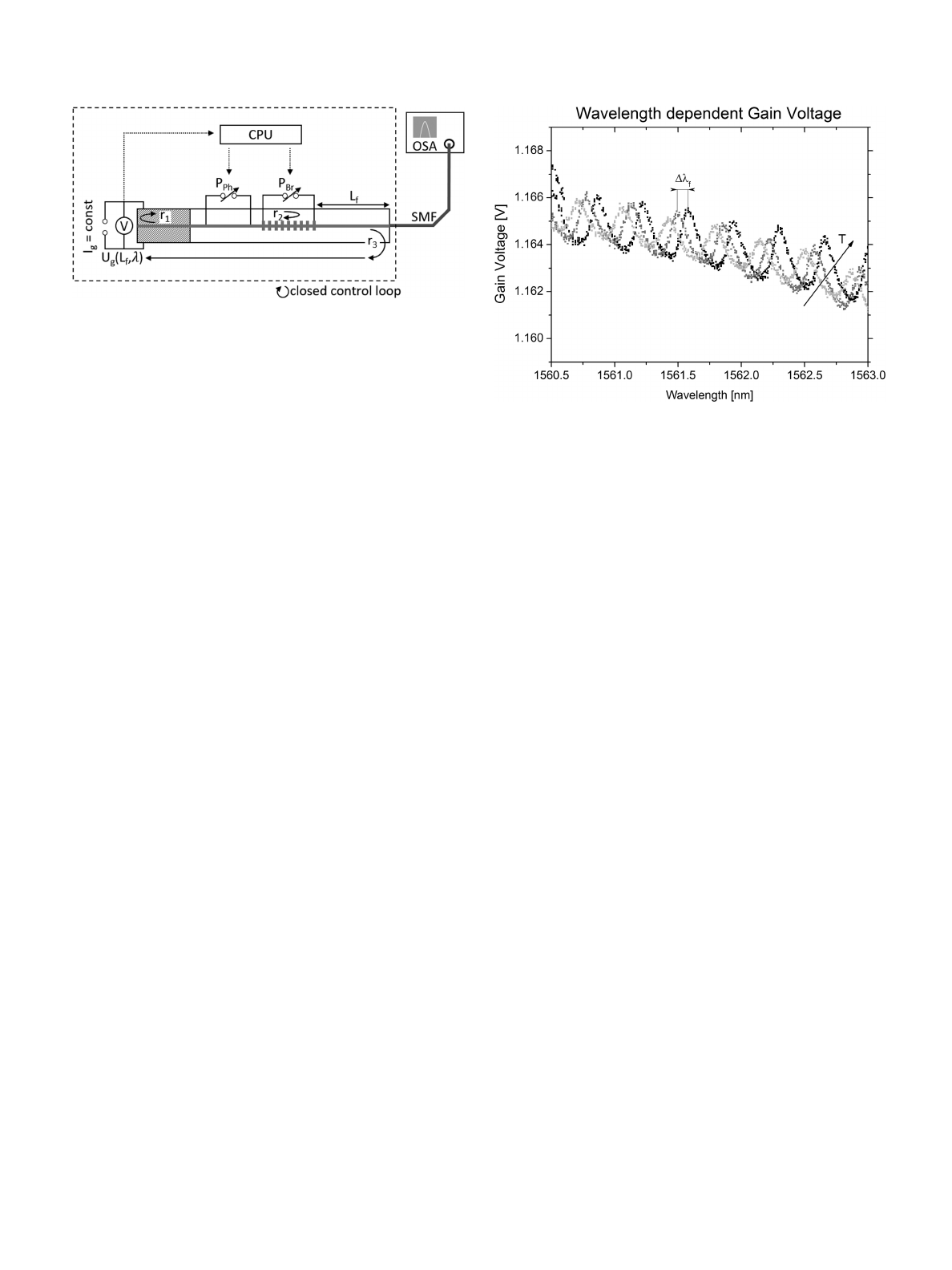
Fig. 1. Measurement setup for wavelength and gain voltage measurement.
The dashed rectangle shows how the setup can be used for mode stabilization.
A constant current is supplied and the voltage is measured. The laser cavity is
formed by the gain chips left facet with reflectivity coefficient r1and the Bragg
grating on the passive platform r2. The wavelength can be tuned by the phase
heating power PPh and the Bragg heating power PBr. The feedback section with
length lfand reflectivity coefficient r3reintroduces part of the laser beam back
into the cavity. The passive and the feedback section are in the same polymer
chip.
In the optical feedback interferometry [12], it is common to
use the voltage as a monitor signal. Here, the voltage serves as
a measure of losses. Light is reflected back from a reflective
surface outside the laser cavity and is then reintroduced into
the laser cavity. Depending on the phase shift between cavity
beam and back reflected beam, interference modulates the cavity
losses. This is a cost saving approach compared to monitoring
the output power because no additional components, like e.g., a
photo diode, are needed [13], [14].
In this paper we use optical feedback to promote the gain
voltage to a monitor signal for wavelength changes as well as a
monitor signal for determining the absolute wavelength.
II. MEASUREMENT SETUP
The measurement setup uses a hybrid Indium phosphide (InP)
polymer laser from the Heinrich-Hertz-Institue (HHI), Fig. 1.
The buried heterostructure-type InP-based gain chip comprises
an MOVPE gwon InGaAsP multi-quantum well active region
[15]. The laser has a tuning range from 1551 to 1564 nm. The
active gain section is supplied with Ig=50 mA of a constant
current source. The applied voltage varies depending of the inter-
nal and mirror loss [9]. The passive section of the laser consists
of a phase section and a distributed Bragg grating (DBR) with
buried heating stripes to enable the wavelength tuning. Applied
electrical power PPh and PBr introduce heating temperature
below the phase and the Bragg section and change the refractive
index by the thermo optical effect. The level of the gain voltage is
monitored by a control unit. The control unit adjusts the heating
powers. The laser cavity is established by a high reflectivity (HR)
r1coating of the left facet of the gain section and the DBR grating
r2. The output waveguide of the laser chip is butt coupled to the
single mode fiber. The coupling point is filled up with index
matching glue. However, the refractive index alignment is not
perfectly and a step index contrast been introduced. Thereby,
a third reflectance r3has been introduced which reflects about
−45 dB of the laser beam back into the laser cavity. Dependent
Fig. 2. Gain voltage trajectory during continuous tuning of a laser with optical
feedback under different module temperatures of 39, 40 and 41 °C.
on the optical length of the feedback section Lfand the emitted
wavelength of the laser, the back reflected beam and the laser
beam interfere constructively/destructively. The loss of the laser
varies. The emitted wavelength and power are monitored by an
optical spectrum analyzer (OSA).
The laser module is glued on a thermo-electric cooler with
heat-conducting adhesive. This design ensures that the same
temperature prevails throughout the entire laser module. The
temperature was measured by a temperature sensor on top of
the passive section of the laser chip.
III. TEMPERATURE SENSITIVITY OF THE LASER SETUP
The optical length of a waveguide can be expressed by L
=n·l with n being the refractive index and l the geometrical
length. Introducing certain heat into the waveguide leads to
optical length change due to the thermal expansion as well as a
thermo optical effect. Having a reflection r3at a certain distance
outside the laser, the optical length of the feedback section is Lf
=nplf. This length defines the maximum positions of the gain
voltage when tuning the laser continuously. Based on the length
of the feedback section and the emitted wavelength, the back
reflected beam interferes constructively/destructively according
to their phase. This kind of gain/loss can be directly measured
by a decrease/increase of the Voltage [9], [11]. Hence, a voltage
level change indicates either a wavelength change or a change in
temperature and with it in the optical length of the feedback sec-
tion. The length variation can be expressed as dLf/dT =ΔLf=
(TOC +npTEC)lfΔT, being TOC the thermo optical coefficient
and TEC the thermal expansion coefficient. Fig. 2 shows the gain
voltage trace for different laser module temperatures of 39, 40
and 40°C. The trace of one wavelength-sweep at 39°C can be
used as input for the theoretical considerations to determine the
optical length. We find (TOC +npTEC) =−7.75·10−5.Using
TOC =−1.1·10−4[15], [16] of the polymer we determine the
thermal expansion coefficient calculated to be TECcalculated =
2.22·10−5. This is about one order of magnitude smaller than
HAPPACH et al.: WAVELENGTH LOCKING AND DETERMINATION IN TUNABLE LASERS BY GAIN VOLTAGE MEASUREMENT 2047
the data given by the manufacturer, TECmanufacturer =30·10−5.
However, the polymer is spin coated on a silicon wafer which
has TECSi =0.47·10−5[17] and hinders the expansion, maybe
causing mechanical stress.
Combining the thermal expansion and the thermo optical
effect in a manner that they compensate each other as shown
in [18], one establishes an athermal feedback section. Another
approach would be the combination of positive TOC materials
such as Silicon nitride and negative TOC materials such as
polymer [19]. Also, placing heating stripes next to the waveguide
could compensate temperature effects by increasing/lowering
the heating power of the waveguide.
IV. APPLICATIONS OF THE GAIN VOLTAGE AS MONITORING
SIGNAL
In this paper we did not rely on a laser design including an
athermal optical feedback section but want to demonstrate that
the gain voltage under optical feedback is a suitable parameter
for wavelength locking applications. The demonstration will
be by keeping the optimal alignment of the lasing mode and
the maximum of the Bragg grating reflection spectra for a
temperature variation from 25 to 35 degree. For this, we use
the gain voltage as a sensor, measuring temperature changes
and adjust the tuning parameters in a manner such that detuning
stays minimal.
A. Mode Stabilization and Wavelength Locking
Changing the laser module’s temperature by ΔT leads to a
change of the optical length of the laser cavity ΔLcav, the grating
period ΔΛ, and the feedback section length ΔLf. It also leads
to a shift of the mode positions ΔλPh, a shift of the maximum
of the reflectivity of the Bragg grating ΔλBand a shift of the
maxima positions of the voltage Δλf. The shifts of ΔλPh and
ΔλBlead commonly to a detuning of the laser because they
generally do not cancel. The change of Δλfleads to a change
of the voltage ΔUg. Therefore, the change of the gain voltage
is only an indirect indicator for a detuning because it simply
indicates a temperature change.
Cavity :ΔT→ΔLcav →ΔλPh →detuning
Bragg :ΔT→ΔΛ →ΔλB→detuning
F eedback :ΔT→ΔLf→Δλf→ΔUg.(1)
1) Algorithm for Mode Stabilization: The algorithm for
mode stabilization is described in [20]. The voltage of the active
section is being used as a monitor signal. The algorithm uses
slope m =ΔPPh/ΔPBr to repeatedly tune across the voltage
extremum to track its position in terms of the tuning parameters
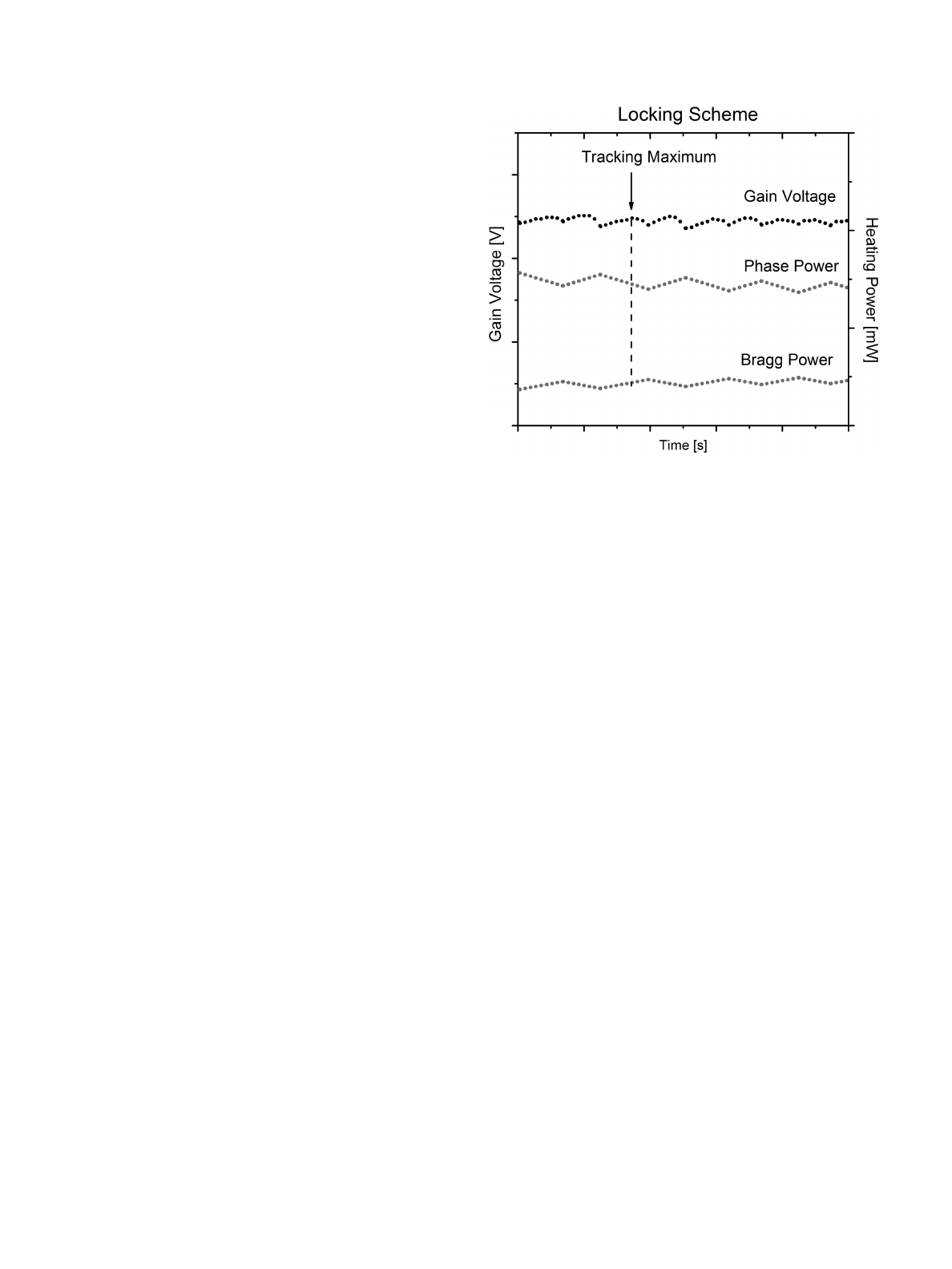
PPh and PBr,Fig.3.
A change of the temperature of the laser module leads to a shift
of the mode hop positions and the gain voltage maximum. The
shift of the maximum can be tracked by the control unit which
tunes the laser to follow the shift. With this form of tracking,
a change in position of the voltage extremum can be detected
in time and the tuning parameters can be adjusted to follow
the extremum, Fig. 3. Using optical feedback from a constant
Fig. 3. Measured gain voltage with active locking algorithm. It sets the heating
powers back and forth to track the gain voltages maximum. The voltage maxima
shift due to a temperature change of the laser module and the phase heating power
is decreased while the Bragg heating power is increased. The heating process
will be repeated periodically to determine the maximum in time.
distance enables the usage of the gain voltage as monitor signal
by direct electrical measurement comparing to [8], [21], [22]
where frequency generators and lock-in amplifiers are needed.
2) Impact of Optical Feedback on the Laser Characteristic:
Optical feedback has an impact on several parameters of the
laser. The extrema of the gain voltage are good reference points.
Tuning a laser on a maximum of the gain voltage grants maximal
output power. Tuning the laser to a minimum of the gain voltage
gives a minimum in linewidth and threshold current [9]. In our
experiments we decided for maximal output power, tracking the
maximum of the gain voltage.
3) Laser With Constant Power at Tuning Sections: In order
to investigate the behavior of the laser at different temperatures,
the heating powers at the tuning section PBr and PPh were kept
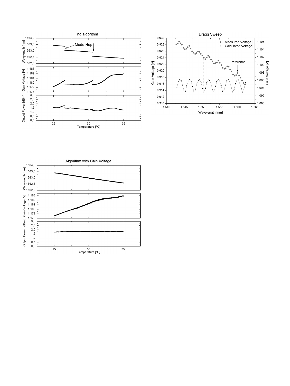
constant while the temperature was varied. Fig. 4. shows that
the wavelength starts to shift when the temperature changes.
After about 3 degrees, a mode hop occurs which can be seen
by an abrupt decrease of the wavelength. The output power
shows variations between 1.0 dBm and 1.75 dBm and a power
discontinuity with the mode hop as well. A mode hop can induce
changes of the output power of up to 0.25 dBm. Additional
measurements of the gain voltage show variations from 1.1820
V to 1.1795 V. When the mode hop occurs, the voltage changes
by 1.5 mV which comes from a decrease of the losses due to the
wavelength dependent loss of the active section.
4) Laser With Feedback Loop for Active Tuning Section
Adjustment: We can redo this experiment, but this time using the
previously described algorithm. Now the gain voltage is used as a
monitor signal of temperature changes and the tuning parameters
are being adjusted to follow the maximum of the voltage. Fig. 5
shows that no mode hop occurs over the tested temperature
2048 JOURNAL OF LIGHTWAVE TECHNOLOGY, VOL. 40, NO. 7, APRIL 1, 2022
Fig. 4. Measured emitted wavelength of the laser at different module temper-
atures without algorithm but constant heating power supply PBr =const, PPh
=const.
Fig. 5. Measured emitted wavelength of the laser at different module temper-
atures with active algorithm which aligns the Bragg and the phase heating power
to stabilize the mode and the output power.
range. Compared to Fig. 4. without the algorithm, the wave-
length shifts in the same range from 1562.4 nm to 1563.4 nm.
The algorithm compensates the misalignment between the lasing
mode and the maximum of the Bragg grating’s reflection by
adjusting the tuning parameters PBr and PPh. Furthermore, the
output power with activated algorithm remains constant at 1.75
dBm.
5) Outlook for Wavelength Locking: The length of the feed-
back section in the passive polymer chip is temperature depen-
dent, hence the voltage trace shifts with temperature changes.
Therefore, in this design setup, the gain voltage is not suitable
to track wavelength changes. However, if the feedback section
is designed to be athermal, meaning dLf/dT ≈0, the voltage can
Fig. 6. Calculated and measured gain voltage for the lasing mode with optical
feedback. The voltage between two mode hops has been averaged to obtain one
voltage point for each excited wavelength mode.
be used for wavelength locking. A possible approach would be
the integration of a heating section similar to the phase heating
section. While monitoring the laser module temperature the
heating power of the feedback section could be controlled to
establish a constant optical length. Also, the composition of two
different materials might be a way to establish a constant optical
length. For example, the negative TOC of the polymer could
compensate the positive TOC of an additional section right after
laser output, which could be realized by a single mode fiber or an
additional chip. However, here a careful design should be used to
make sure no additional reflection at the coupling point between
positive and negative TOC section is introduced. Whereby the
design rules of [10] can help to minimize the influence of optical
feedback on the tuning characteristic.
B. Wavelength Determination
In the previous section we explained how to use the gain
voltage to track relative changes of the wavelength. In this
section we propose an algorithm to determine the absolute lasing
wavelength by analyzing the gain voltage.
Performing a Bragg sweep samples the gain voltage with a
too low wavelength resolution and causes an aliasing effect such
that one would see a frequency of the wavelength oscillation
far lower than the actual sinusoidal shape. Fig. 6 shows the
measured aliasing trace for a Bragg sweep and the corresponding
calculated voltage [11]. The oscillation of the voltage is defined
by the length difference between the laser cavity Lcav and the
feedback cavity Lf. When the two lengths are known, either by
design or initial measurement, one would know which peak of
the aliased gain voltage represents which wavelength. In our
example we used the peak at λ=1560.12 nm as a reference,
Fig. 6. First, we performed a Bragg sweep to determine the
mode by the maximal voltage. Second, we tuned the laser
continuously. The free spectral range (FSR) of the gain voltage
is 0.35 nm and determined by the length Lfof the feedback
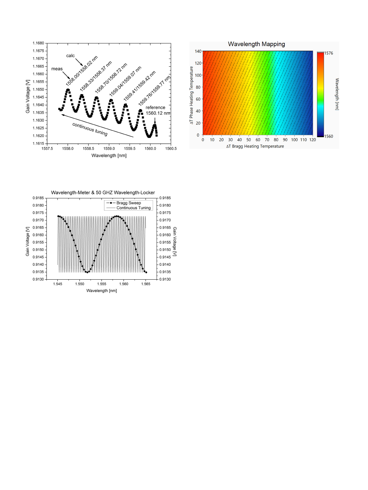
section. The calculated and measured peak positions are shown
in Fig. 7.
HAPPACH et al.: WAVELENGTH LOCKING AND DETERMINATION IN TUNABLE LASERS BY GAIN VOLTAGE MEASUREMENT 2049
Fig. 7. Measured gain voltage trace with measured and calculated peak
wavelengths.
Fig. 8. Spectra of continuous tuning and a Bragg sweep shows a proposal of a
laser with integrated wavelength-meter based on the aliasing effect. The voltage
variations during the continuous tuning can be used as a wavelength locking
signal.
V. DESIGN PROPOSAL
A wavelength-meter with a FSR =50 GHz of the gain voltage
would have a feedback section length of 2998 µm and a laser
cavity length of 2998 +90 µm. The design would result into
a spectrum like shown in Fig. 8. The different lengths of the
laser cavity and the feedback cavity create an aliasing in the
gain voltage while performing a Bragg sweep. The free spectral
range of the aliased signal is based on the length difference of
the cavities. The stability of the optical length of both cavity
is mandatory for accurate wavelength determination. Tuning
the Bragg section also changes the length of the laser cavity
by changing the penetration depth. However, this effect can be
compensated by simultaneous tuning the phase section. Once
the maximum of the aliased signal has been found, continu-
ous tuning can be performed to adjust the heating power to a
maximum of the gain voltage. The maximum can then be used
Fig. 9. Calculated wavelength mapping of the laser with proposed integrated
wavelength-meter.
as a monitor signal for wavelength changes when the feedback
section is athermal.
The length of the laser cavity and the feedback section differ
only by 90 µm. Thus, the ratio between the cavity is still a
whole number and follows the design rule [10] for stable laser
tuning setups of a laser under optical feedback. The calculated
wavelength mapping of Fig. 9 shows that the mode hop areas,
marked as black lines, are straight and continuous tuning can
be achieved by linear adjustment of the Bragg and the phase
heating temperature.
VI. CONCLUSION
In this paper we used integrated optical feedback to make
the gain voltage wavelength dependent which enables various
applications. It has been demonstrated that the gain voltage is a
suitable parameter to determine the combined parameters TEC
and TOC, or assuming a known TOC, the absolute TEC of a
composite material. Furthermore, it has been shown that the gain
voltage is a suitable parameter to monitor temperature changes
of the lasing module. These causes a detuning of the lasing
mode and the Bragg grating. Tracking voltage changes allows
to reestablish the alignment. With a proposed approach for an
athermal feedback section design the gain voltage can be used
as a wavelength-locker signal and allows low-cost wavelength
locked lasers. Furthermore, the aliasing effect in the gain voltage
during a Bragg sweep has been used to determine the absolute
wavelength of the emitted laser beam which shows the feasibility
of lasers with integrated wavelength-meter based on non-optical
but electrical measurements.
REFERENCES
[1] J. Zhu et al., “Athermal colorless C-band optical transmitter system for pas-
sive optical networks,” J. Lightw. Technol., vol. 32, no. 22, pp. 4253–4260,
15 Nov., 2014, doi: 10.1109/JLT.2014.2354058.
[2] S. Pachnicke et al., “Centralized, pilot-tone-based wavelength-locking for
WDMPON with 1 GbE data rate,” in Proc. 2013 ITG Symp. Proc. - Photon.
Netw., pp. 1–4.
Loading more pages...