
fluids
Article
Switching Action of a Bistable Fluidic Amplifier for
Ultrasonic Testing
Thorge Schweitzer 1,2,* , Marla Hörmann 1,2 , Benjamin Bühling 1,3 and Bernhard Bobusch 2
Citation: Schweitzer, T.; Hörmann,
M.; Bühling, B.; Bobusch, B.
Switching Action of a Bistable Fluidic
Amplifier for Ultrasonic Testing.
Fluids 2021,6, 171. https://doi.org/
10.3390/fluids6050171
Academic Editors: Pavel Berloff and
Rene Woszidlo
Received: 26 February 2021
Accepted: 15 April 2021
Published: 25 April 2021
Publisher’s Note: MDPI stays neutral
with regard to jurisdictional claims in
published maps and institutional affil-
iations.
Copyright: © 2021 by the authors.
Licensee MDPI, Basel, Switzerland.
This article is an open access article
distributed under the terms and
conditions of the Creative Commons
Attribution (CC BY) license (https://
creativecommons.org/licenses/by/
4.0/).
1Institute of Fluid Dynamics and Technical Acoustics, Technische Universität Berlin, Müller-Breslau-Straße 8,
2FDX Fluid Dynamix GmbH, Rohrdamm 88, 13629 Berlin, Germany; [email protected]
3Bundesanstalt für Materialforschung und -prüfung (BAM), Division 8.2 “Non-Destructive Testing Methods
for Civil Engineering”, Unter den Eichen 87, 12205 Berlin, Germany
*Correspondence: [email protected]
Abstract:
Air-coupled ultrasonic testing is widely used in the industry for the non-destructive
testing of compound materials. It provides a fast and efficient way to inspect large concrete civil
infrastructures for damage that might lead to catastrophic failure. Due to the large penetration depths
required for concrete structures, the use of traditional piezoelectric transducer requires high power
electric systems. In this study, a novel fluidic transducer based on a bistable fluidic amplifier is
investigated. Previous experiments have shown that the switching action of the device produces a
high-power broadband ultrasonic signal. This study will provide further insight into the switching
behaviour of the fluidic switch. Therefore, parametric CFD simulations based on compressible
supersonic RANS simulations were performed, varying the inlet pressure and velocity profiles for
the control flow. Switching times are analyzed with different methods, and it was found that these
are mostly independent of the slope of the velocity profile at the control port. Furthermore, it was
found that an inversely proportional relationship exists between flow velocity in the throat and
the switching time. The results agree with the theoretical background established by experimental
studies that can be found in the literature.
Keywords:
ultrasound; non-destructive testing; fluidic devices; computational fluid dynamics;
concrete; bistable fluidic amplifier
1. Introduction
The recent collapse of the Caprigliola-Bridge [
1
,
2
] in northern Italy and Genoa’s
Morandi-Bridge [
3
] have shown the need for comprehensive testing and health-monitoring
systems for concrete civil infrastructures. Ultrasonic inspections are state-of-the-art meth-
ods of detecting damage and providing insight into the inner structures and reinforcements
present in an object [
4
]. Standard industrial practice is the use of the pulse-echo-method
with contact-based systems [
5
,
6
]. However, these measurements are time-consuming and,
therefore, only financially feasible for small areas where damage is expected. Air-coupled
ultrasonic (ACU) testing can alleviate these issues and provide fast and efficient scanning
of large areas. However, the currently available systems use piezoelectric transducers in
through-transmission setups and have small penetration depths in concrete [
7
,
8
]. They
also require high-powered electrical supplies and other sensitive equipment to generate
the ultrasound signal.
To provide robust means of testing large concrete structures a fluidic transducer based
on a bistable fluidic amplifier was developed. Initial research conducted in [
9
] have shown
that the generation of a broadband ultrasonic signal between 30 kHz and 80 kHz is possible.
Fluidic devices also include fluidic oscillators [
10
,
11
] that have offered many solutions to
modern engineering problems. However, fluidic amplifiers have not seen as much use.
Bobusch and Tesar [
12
,
13
] have shown their application as high-speed gas valves in harsh
Fluids 2021,6, 171. https://doi.org/10.3390/fluids6050171 https://www.mdpi.com/journal/fluids
Fluids 2021,6, 171 2 of 13
environments. They are also used to create high-frequency oscillators by establishing a
feedback, either by attaching a resonator to one of the control ports [
14
] or by connecting
each output channel with the corresponding control port [15]. Roger and Chan presented
a parametric numerical study in 2003 [
16
] that varied different geometrical values and
showed the validity of computational fluid dynamics (CFD) for the design of bistable
fluidic amplifiers. To the authors knowledge, no further research has been published on
the subject. An extensive overview of the early development and research can be found at
Kirschner and Katz [17,18].
In comparison with traditional actuators, fluidic devices are virtually maintenance-
free due to the lack of moving parts. They are also insensitive to radiation and temperature
changes, can be run from a simple pressure reservoir and are not affected by dust or dirty
environments. This makes them ideal for the rough conditions of outdoor testing that often
make the use of piezoelectric or alternative ACU transducers challenging. Furthermore,
most kinds of working fluid, either liquid or gaseous, can be used.
Additional information on the functioning and application of fluidic devices may be
found in the works of Gregory [19], Tesar [20], Foster [21], Raghu [22], and Bobusch [12].
In this study, parametric CFD simulations based on compressible supersonic Reynolds
averaged Navier–Stokes (RANS) simulations will be performed to investigate parameters
influencing the switching time. Experimental investigations have shown that the acoustic
field of the transducer can be modeled as a rectangular piston in a rigid baffle. This renders
the switching time as the main influence on the gradient of the model piston speed and
the resulting pressure wave. To determine the effect of different switching valves on the
performance of the amplifier, varying control flow profiles will be used. Furthermore, to
investigate the influence of flow velocity, different inlet pressures will be applied. Lastly,
the inlet pressure will be set to a constant value and the size of the amplifier will be varied.
2. The Fluidic Transducer
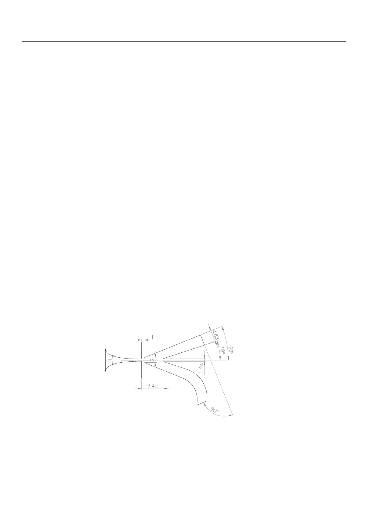
The fluidic transducer is based on a bistable fluidic amplifier. The dimensions are
shown in Figure 1and are mainly based on the fluidic switch used by Bobusch [
12
]. The
system was scaled down to greatly reduce the switching time and allow the excitation of
ultrasonic waves. Furthermore, to allow for better acoustic shielding, the lower output
channel was curved to a 90° angle from the upper outlet.
Figure 1.
The bistable fluidic amplifier used in the design of the transducer with dimensions in mm.
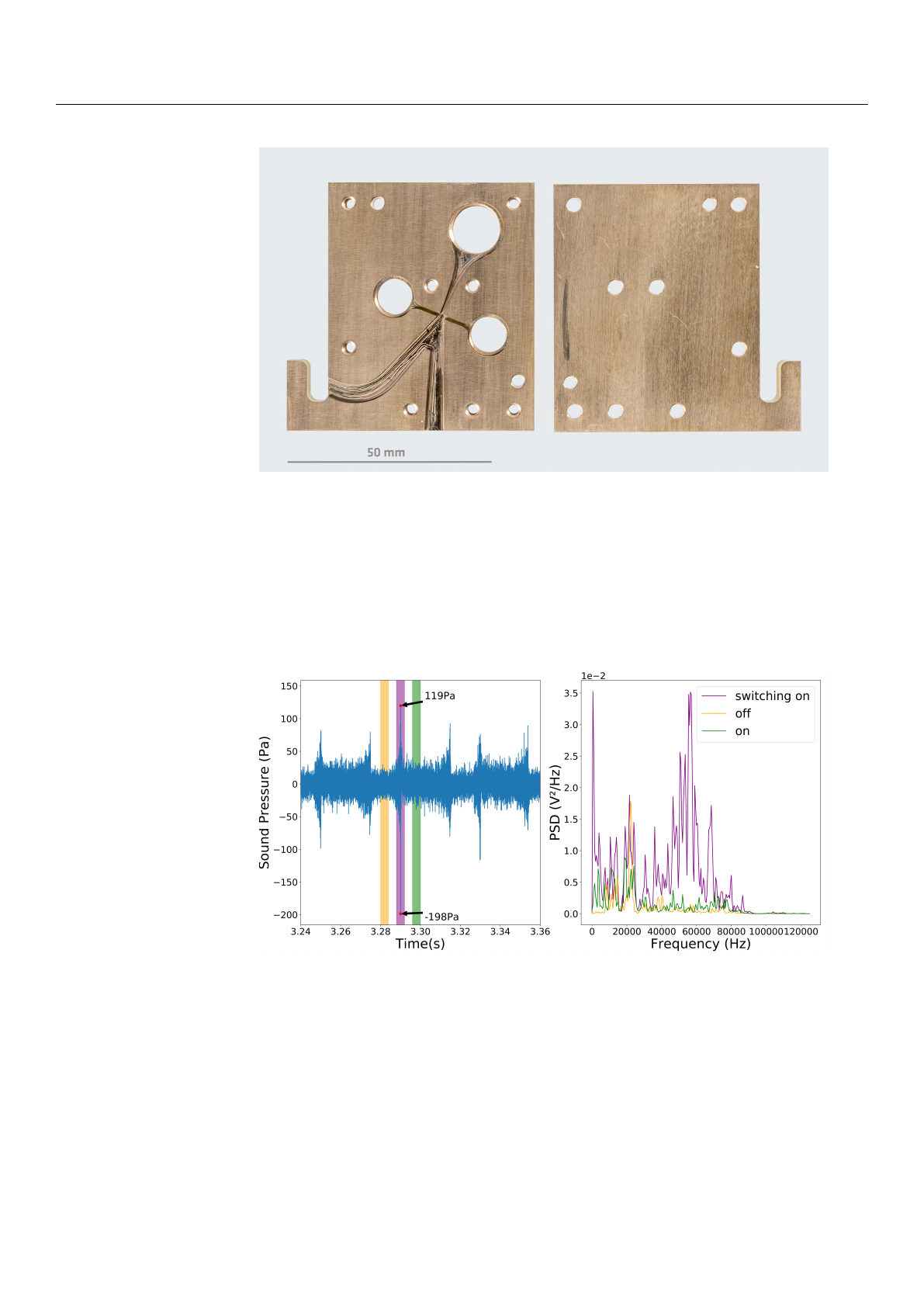
Figure 2shows the prototype that was built from brass. It has an extrusion depth of
1mm and was CNC-milled in the workshop of the Bundesanstalt für Materialforschung
und -prüfung (BAM).
Fluids 2021,6, 171 3 of 13
Figure 2. Initial protoype of the fluidic transducer made from brass.
Figure 3on the left shows a time series that was obtained with the measurement
microphone Microtech Gefell MV301 in combination with a MV302 pre-amplifier about
20 mm from the outlet and the resulting spectrum. The coloured sections in the left plot
mark the different states of the fluidic transducer and the corresponding spectra are shown
in the right plot. The switching action of the device, signified by the pink area, produces a
strong pulse of about 138 dB with a broadband ultrasonic spectrum between 30 kHz and
80 kHz.
Figure 3.
Time series of the sound pressure and power density spectrum (PSD) measured with the
inital prototype.
3. Methods
3.1. Governing Equations
The motion of a compressible flow is described by the conservation of momentum,
mass and energy. OpenFOAM uses the hyperbolic form of the conservation laws, with
F(W)
as the flux function. With the Reynolds decomposition, we arrive at the Unsteady
Reynolds Averaged Navier Stokes equations (URANS). In hyperbolic form, these are
W=
ρ
ρu
ρE
,F(W) =
ρu
ρuu +pI
ρEu +pu
−
0
σ
σu+κe f f ∇T
(1)

Fluids 2021,6, 171 4 of 13
ρ
u,pand Tare the density, velocity, pressure and temperature, respectively. I desribes
the unit tensor and the specific total energy
E
is the combination of the specific internal
energy
e
and the specific kinetic energy described by
u2/
2. The coupling of density and
pressure is achieved by the ideal gas law with
p= (κ−
1
)ρe
and
κ
as the specific heat
capacity. σdescribes the vicious-turbulent stress tensor and is given by
σ=µe f f ∇u+ (∇u)T−2I
3∇uwith µe f f =µ+µt(2)
µ
is calculated as a function of temperature with the Sutherland transport model while
µt
is modeled by the chosen turbulence model.
3.1.1. Numerical Setup
Mesh
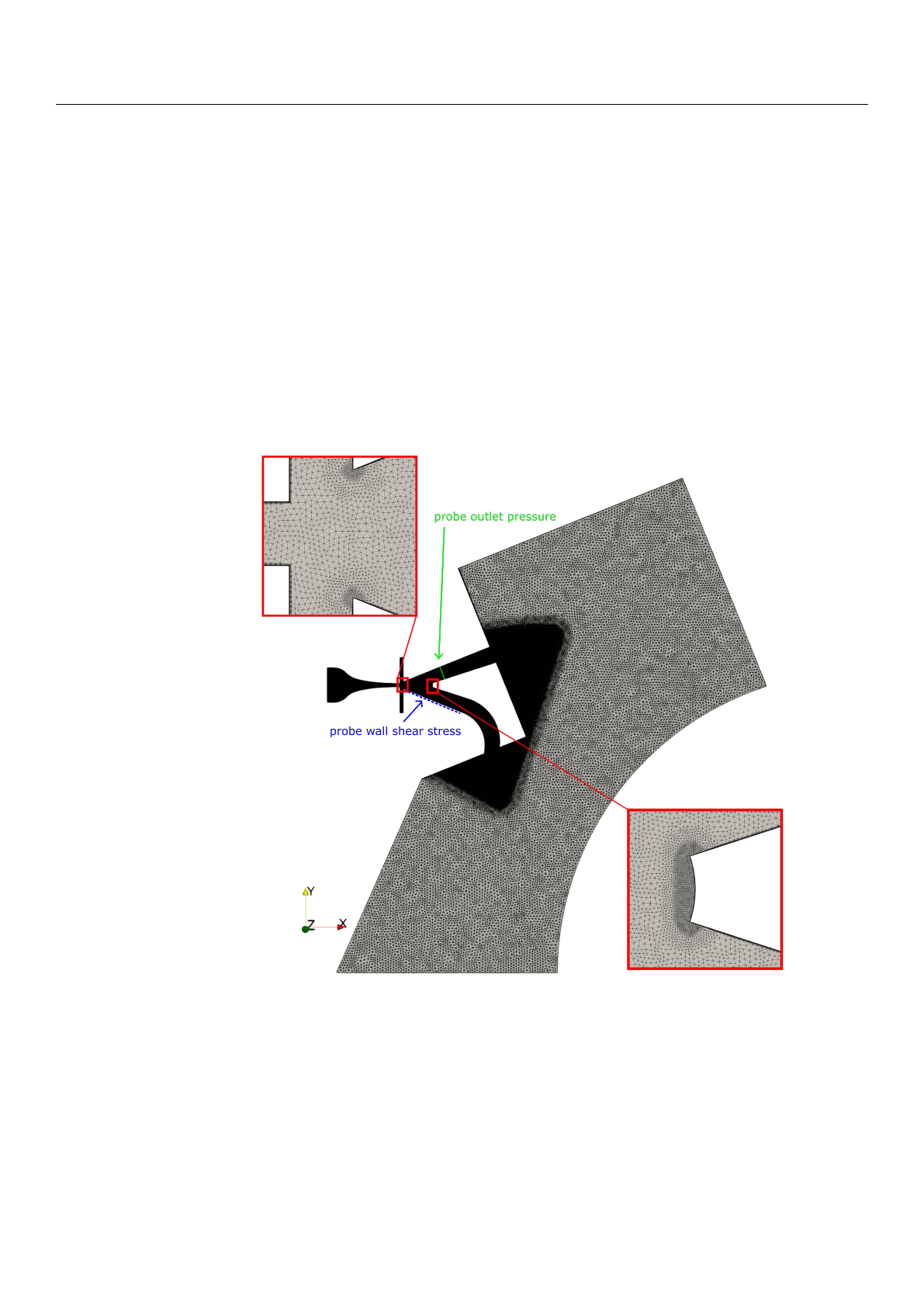
Ansys ICEM CFD was used to construct the 2D mesh. The mesh is a tetrahedron dom-
inant unstructured mesh, with seven prism layers along the walls. A mesh independence
study was performed using four different mesh sizes from 120.202 to 572.666 elements.
The mesh with 355.432 nodes showed no significant differences in flow characteristics and,
therefore, was used. Characteristic values are a maximum skewness of 3.7 and a maximum
non-orthogonality of 50.1. The farfield has a characteristic cell size (CCS) of 1 mm.
The mesh includes two refinement levels. The first one covers the inside of the switch
and the near field with a CCS of 0.1 mm, the second one improves resolution at prominent
structures where high gradients are expected, like the splitter with a ccs of 0.025 mm. These
three size levels are visualized in the illustration of the mesh in Figure 4.
Solver
To allow for reproduction of the achieved results, the URANS equations are solved
using the rhoCentralFoam solver of the open source software OpenFOAM 6.0 However, the
accuracy of numerical results is heavily dependent on the numerical scheme employed,
especially for the supersonic flow regime in the presented transducer. Shock systems can
have significant impact on the flow behavior and need to be appropriately resolved. To im-
prove the resolution of shocks, significant research has been done in the last 30 years. Some
examples can be found in Barton et al. [
23
], Zoltak et al. [
24
] and Harten [
25
]. Toro [
26
]
provides the theoretical background of different schemes and an extensive comparison
between them. rhoCentralFoam is a density-based compressible flow solver based on the
central-upwind schemes of Kurganov and Tadmor. Kurganov and Tadmor expanded on
the Nessyahu and Tadmor central scheme [
27
], based on the Lax–Friedrich method [
28
],
severely improved the numerical dissipation behaviour and showed good accuracy for
shock simulations [
29
]. Furthermore, Marcantoni et al. [
30
] showed a better agreement for
supersonic flows for rhoCentralFoam than the alternative sonicFoam solver, which is based
on the PISO algorithm. The basic settings of the solver, such as the discretization types,
were used. A first-order implicit Euler scheme is used for the temporal discretization and a
second-order scheme is used for the local discretization. To ensure stability, the maximum
time step was set by enforcing the Courant–Friedrichs–Lewy (CFL) number to stay below
0.4. The two-equation model k-ω-SST [31] is used to model the turbulence.
Boundary Conditions
A mixture of fixed pressures and velocity inlets was used for the boundary conditions.
The flow rate is specified at the main inlet via a fixed pressure to emulate the previous
experimental setup. At the two control ports, time-varying velocities are specified due to
the unknown pressure in the non-active states. Furthermore, pressure inlets would allow
an inflow due to entrainment by the main jet, which does not accurately represent the
experimental conditions. The walls are no-slip walls with characteristic wall functions
for each turbulent quantity. Due to limited computing capacity, the far field was shaped
according to the expected jet path and the corresponding outlets are set to a wave trans-
Fluids 2021,6, 171 5 of 13
missive pressure boundary condition to eliminate the influence of wave reflection in the
compressible case. The rest of the outlet areas are set to a fixed ambient pressure. To allow
free entrainment by the jet in the far field, the outlet velocity condition is set to inletOutlet.
The top and bottom patches of the domain are set to an empty boundary condition to
realize a 2D case in OpenFOAM. All remaining boundary conditions are taken from the
basic setup for the solver.
3.2. Switching Times
Two methods will be used to characterize the switching times. First, the averaged
pressure over the top output channel will be analysed. The corresponding probe is marked
in green in Figure 4. Since the bistable fluidic amplifier will be used as an ultrasonic
transducer, pressure-based evaluation is an obvious choice. Even though compressible
URANS simulations are not able to accurately predict acoustics, the pressure distribution
provides valuable insight into the switching action.
Figure 4.
2D unstructured Mesh for the parametric simulation with 355.432 nodes and data probes
for the evaluation.
Subsequently the local wall shear stress is analysed along the blue probe. This method
is inspired by [
32
] who used the movement of the reattachment point, and, therefore, the
movement of the zero-crossing of the wall shear stress behind the recirculation bubble, as a
criterium for the switching time. Three distinct areas can be defined:
1.
Increasing size of the recirculation bubble—the reattachment point moves down-
stream;
2.
Maximum size of the recirculation bubble—the reattachment point stops moving
downstream;
Loading more pages...