
catalysts
Communication
Influence of Phase Composition and Pretreatment on the
Conversion of Iron Oxides into Iron Carbides in
Syngas Atmospheres
Aleks Arinchtein 1, Meng-Yang Ye 1, Michael Geske 2, Marvin Frisch 1and Ralph Kraehnert 1,*
Citation: Arinchtein, A.; Ye, M.-Y.;
Geske, M.; Frisch, M.; Kraehnert, R.
Influence of Phase Composition and
Pretreatment on the Conversion of
Iron Oxides into Iron Carbides in
Syngas Atmospheres. Catalysts 2021,
11, 773. https://doi.org/10.3390/
catal11070773
Academic Editor: Simone Mascotto
Received: 20 May 2021
Accepted: 24 June 2021
Published: 25 June 2021
Publisher’s Note: MDPI stays neutral
with regard to jurisdictional claims in
published maps and institutional affil-
iations.
Copyright: © 2021 by the authors.
Licensee MDPI, Basel, Switzerland.
This article is an open access article
distributed under the terms and
conditions of the Creative Commons
Attribution (CC BY) license (https://
creativecommons.org/licenses/by/
4.0/).
1Department of Chemistry, Technische Universität Berlin, Strasse des 17. Juni 124, D-10623 Berlin, Germany;
2BasCat—UniCat BASF JointLab, Technische Universität Berlin, Hardenbergstraße 36,
*Correspondence: [email protected]; Tel.: +49-30-314-23518
Abstract:
CO
2
Fischer–Tropsch synthesis (CO
2
–FTS) is a promising technology enabling conver-
sion of CO
2
into valuable chemical feedstocks via hydrogenation. Iron–based CO
2
–FTS catalysts
are known for their high activities and selectivities towards the formation of higher hydrocarbons.
Importantly, iron carbides are the presumed active phase strongly associated with the formation of
higher hydrocarbons. Yet, many factors such as reaction temperature, atmosphere, and pressure can
lead to complex transformations between different oxide and/or carbide phases, which, in turn, alter
selectivity. Thus, understanding the mechanism and kinetics of carbide formation remains challeng-
ing. We propose model–type iron oxide films of controlled nanostructure and phase composition as
model materials to study carbide formation in syngas atmospheres. In the present work, different
iron oxide precursor films with controlled phase composition (hematite, ferrihydrite, maghemite,
maghemite/magnetite) and ordered mesoporosity are synthesized using the evaporation–induced
self–assembly (EISA) approach. The model materials are then exposed to a controlled atmosphere of
CO/H
2
at 300
◦
C. Physicochemical analysis of the treated materials indicates that all oxides convert
into carbides with a core–shell structure. The structure appears to consist of crystalline carbide cores
surrounded by a partially oxidized carbide shell of low crystallinity. Larger crystallites in the original
iron oxide result in larger carbide cores. The presented simple route for the synthesis and analysis of
soft–templated iron carbide films will enable the elucidation of the dynamics of the oxide to carbide
transformation in future work.
Keywords: CO2Fischer–Tropsch synthesis; iron oxide; iron carbides; mesoporous films; EISA
1. Introduction
The ongoing increase in atmospheric levels of CO
2
is one of the major reasons for
pronounced global warming and climate change over the last decades on earth [
1
,
2
].
Thus, great efforts were recently made to develop technologies for CO
2
reduction [
3
–
5
].
CO
2
Fischer–Tropsch synthesis (CO
2
–FTS) is a promising approach to convert CO
2
with
hydrogen (H
2
) into olefins (C
2
–C
4
alkenes), which are important feedstocks for the chemical
industry [
6
,
7
]. The reaction has been reported to proceed in two steps: the reverse water
gas shift reaction (RWGS), which reduces CO
2
to CO, and a subsequent hydrogenation of
CO, i.e., a typical CO Fischer–Tropsch synthesis (CO–FTS). Iron–based catalysts, such as
hematite (
α
–Fe
2
O
3
), are able to catalyze both reactions under similar reaction conditions
and show high selectivities toward higher hydrocarbons [
6
–
8
]. Therefore, it is of great
importance to develop stable and highly efficient iron–based CO2–FTS catalysts.
Iron–based catalysts were shown to undergo a complex dynamic structural change
during the CO
2
–FTS process.
α
–Fe
2
O
3
, a typical starting material, can be converted under
the employed reducing conditions into many different phases under the conditions of the
Catalysts 2021,11, 773. https://doi.org/10.3390/catal11070773 https://www.mdpi.com/journal/catalysts

Catalysts 2021,11, 773 2 of 11
CO
2
–FTS—such as wustite (FeO), maghemite (
γ
–Fe
2
O
3
), magnetite (Fe
3
O
4
), elemental iron
(Fe), and iron carbides. Each of these phases may potentially form species which affect
both activity and selectivity of the catalyst [8–11].
Previous studies indicate that iron carbides are favorable for the formation of higher
hydrocarbons [
12
]. Schroff et al. investigated Fe
3
O
4
catalysts in the CO
2
–FTS. In their
study, pristine Fe
3
O
4
was observed to show hardly any catalytic activity for the CO–FTS.
More importantly, the formation of a carbide phase turned out to be of pivotal importance
to obtain high catalytic activities [
13
]. Herranz et al. used pure hematite catalysts, tracing
the formation of cementite (
θ
–Fe
3
C) and Hägg iron (
χ
–Fe
5
C
2
) during a pretreatment
in a mixture of gaseous CO/H
2
. Beyond that, the authors revealed the formation of
carbonaceous intermediate species on the surface of Hägg iron (
χ
–Fe
5
C
2
) carbides, which
are claimed to be more active for the CO
2
–FTS [
9
]. Moreover, Yao et al., reported the use
of syngas treatments prior to CO
2
–FTS as an elegant way to activate the catalysts [
14
].
A comprehensive review on syngas–induced carbide formation, related iron oxide and
carbide phases, challenges in material characterization, and deactivation mechanisms has
been reported by de Smit and Weckhuysen in 2008 [11].
Additionally, the structure of the catalyst has a great impact on catalytic performance
and carbide formation. Galvis et al., reported significant particle size effects for supported
iron carbides [
15
]. Different studies focused on the addition of promotors. Alkali metals
e.g., potassium were reported to enhance the catalytic performance [
11
,
16
]. Galvis et al.,
studied sodium and/sulfur promoted catalysts and observed increased carbide contents
depending on the sodium/sulfur concentration. The results showed that not necessarily
the highest carbide content results in the best performing catalyst [17].
In the recent years, sophisticated characterization techniques in the field of surface
analysis led to an identification of formed iron carbide phases and other carbonaceous
intermediate species on iron–based catalysts in CO
2
–FTS [
18
]. Nonetheless, understanding
the carbide formation process under the CO
2
–FTS reaction conditions still remains a
challenge. Iron oxides can show various crystal structures and different phases, which,
accordingly, obstruct clear conclusions due to the heterogeneity of the studied catalysts [
8
,
9
].
Moreover, these materials are sensitive to changes in temperature, time on stream, applied
pressure, humidity, gases (air, H
2
, CO, CO
2
) during CO
2
–FTS [
6
–
8
]. Beyond that, rather
low crystallinities of the intermediate phases and complex nature of the surface species
on iron–based catalysts in CO
2
–FTS process make a clear identification of the carbide
phases among other possible intermediate phases difficult. Therefore, in order to develop
an efficient guideline for designing high performance iron–based CO
2
–FTS catalysts, a
fundamental understanding for the dynamic and mechanistic behavior has to be achieved.
In a first step, we investigate the formation of carbides in CO/H
2
mixtures, i.e., treatments
that favor rapid carbide formation and can be used to activate CO2–FTS catalysts.
Herein, we introduce an approach to use model–type iron oxide films with a well–
defined mesoporous structure to shed light on the formation of carbides upon exposure
to synthesis gas on different length scales. Physicochemical properties were assessed by
complementary bulk– and surface–sensitive analysis techniques. The mesoporous iron
oxide films can be synthesized with different initial phase composition as established
in our previous work, i.e., hematite [
19
], ferrihydrite, [
19
] maghemite [
20
] as well as a
maghemite partially converted into magnetite [
20
]. We previously employed this approach
to investigate phase transformation and crystallization behavior of iron oxides and/or –
oxohydroxides upon exposure to air, [
19
] N
2
, [
20
] Ar/H
2
[
20
] as well as the role of water [
21
]
in oxide phase transformations.
Briefly, the model–type oxide films are prepared using the well–established EISA
approach with block–copolymer micelles as soft template for the introduction of a meso-
porous structure [
22
,
23
]. It enables synthesis of well–ordered mesoporous thin films with
tunable composition, crystallite size and wall thickness [
24
,
25
]. The as–synthesized or-
dered mesoporous films enable a precise investigation of bulk–averaged information (e.g.,
XRD) and study of local changes in the phase composition, i.e., domain growth on the
Catalysts 2021,11, 773 3 of 11
nanometer scale using microscope methods such as SEM, TEM, and SAED. Beyond that,
thin mesoporous iron oxide films can avoid the shortcomings of typical nanoparticles such
as low accessibility, pronounced agglomeration or ill–defined particle shapes which were
shown to cause difficulties in the studies of in situ surface reactions [14,15,26–28].
In this work, different iron oxide phases with template–controlled mesopore structure,
i.e., hematite (HEM), ferrihydrite (FH), maghemite (MAGH), and maghemite/magnetite
(MAGH/MAGN) were exposed to syngas and studied via different analytical methods
prior and after syngas treatment to understand the phase transformation and crystallization
into carbides. To the best of our knowledge no mesoporous carbide films have been
reported. The developed models present a powerful tool for mechanistic studies also under
conditions of the CO2–FTS.
2. Results
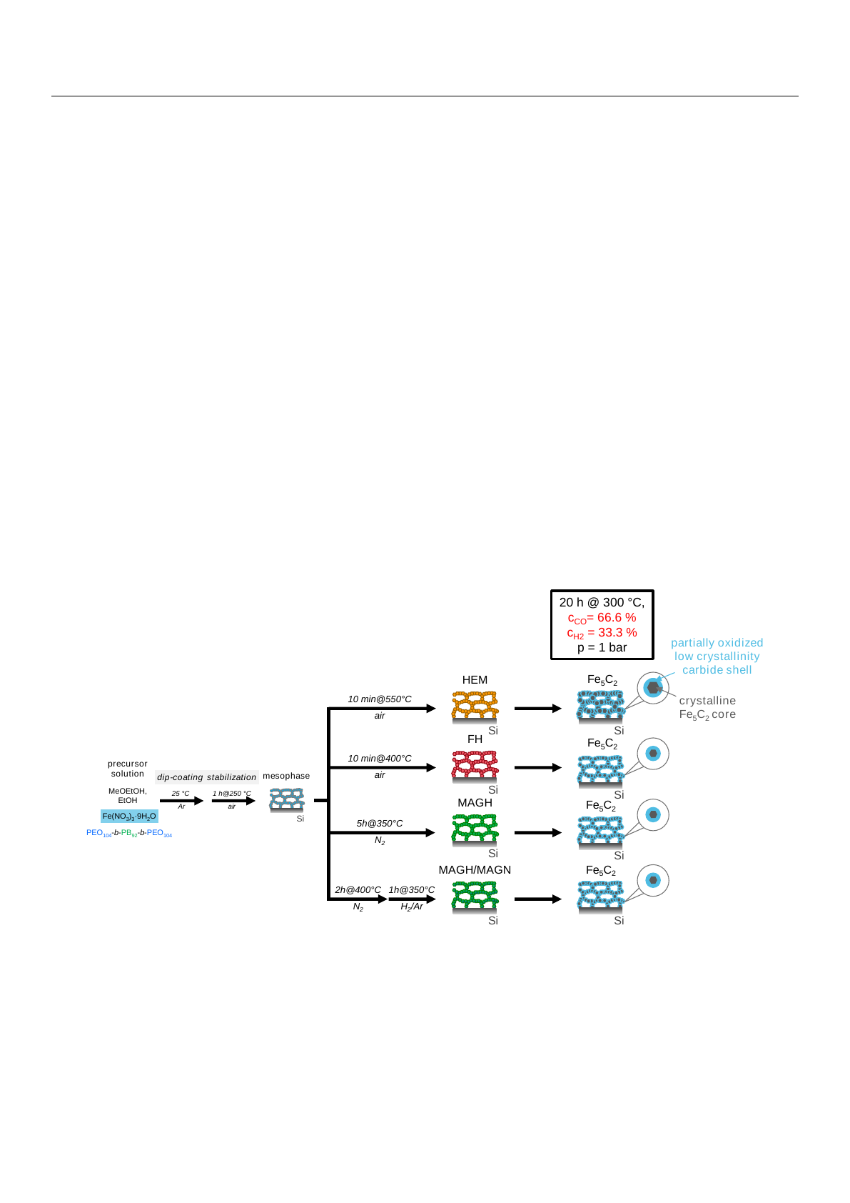
The preparation of the mesoporous iron oxide films via the EISA approach is outlined
in Scheme 1, including the syngas treatment applied to the precursor films in the right
column. Typically, the fresh iron oxide samples were prepared based on a previous
report [
19
,
20
]. Briefly, as a first step, a low crystalline mesophase is produced via dip–
coating in argon atmosphere and stabilization at 250
◦
C in air. Calcination in air at 400
◦
C
for 10 min yields ferrihydrite films (FH) with a well–ordered mesoporous structure and low
crystallinity, whereas calcination at 550
◦
C for 10 min forms a highly crystalline hematite
film (HEM). Maghemite films (MAGH) are obtained after a heat treatment of the mesophase
in N
2
at 350
◦
C for 5 h. Partial reduced maghemite/magnetite films (MAGH/MAGN) form
after a heat treatment in N
2
at 400
◦
C for 2 h followed by a reduction in H
2
/Ar at 350
◦
C
for 1 h.
Catalysts 2021, 11, x FOR PEER REVIEW 3 of 11
tunable composition, crystallite size and wall thickness [24,25]. The as–synthesized or-
dered mesoporous films enable a precise investigation of bulk–averaged information (e.g.,
XRD) and study of local changes in the phase composition, i.e., domain growth on the
nanometer scale using microscope methods such as SEM, TEM, and SAED. Beyond that,
thin mesoporous iron oxide films can avoid the shortcomings of typical nanoparticles such
as low accessibility, pronounced agglomeration or ill–defined particle shapes which were
shown to cause difficulties in the studies of in situ surface reactions [14,15,26–28].
In this work, different iron oxide phases with template–controlled mesopore struc-
ture, i.e., hematite (HEM), ferrihydrite (FH), maghemite (MAGH), and maghemite/mag-
netite (MAGH/MAGN) were exposed to syngas and studied via different analytical meth-
ods prior and after syngas treatment to understand the phase transformation and crystal-
lization into carbides. To the best of our knowledge no mesoporous carbide films have
been reported. The developed models present a powerful tool for mechanistic studies also
under conditions of the CO2–FTS.
2. Results
The preparation of the mesoporous iron oxide films via the EISA approach is outlined
in Scheme 1, including the syngas treatment applied to the precursor films in the right
column. Typically, the fresh iron oxide samples were prepared based on a previous report
[19,20]. Briefly, as a first step, a low crystalline mesophase is produced via dip–coating in
argon atmosphere and stabilization at 250 °C in air. Calcination in air at 400 °C for 10 min
yields ferrihydrite films (FH) with a well–ordered mesoporous structure and low crystal-
linity, whereas calcination at 550 °C for 10 min forms a highly crystalline hematite film
(HEM). Maghemite films (MAGH) are obtained after a heat treatment of the mesophase
in N2 at 350 °C for 5 h. Partial reduced maghemite/magnetite films (MAGH/MAGN) form
after a heat treatment in N2 at 400 °C for 2 h followed by a reduction in H2/Ar at 350 °C for
1 h.
In order to study the impact of the phase composition on the carbide formation, all
oxide films were exposed to syngas (66% CO, 33% H2) at 300 °C for 20 h at atmospheric
pressure.
Scheme 1. Synthetic approach for mesoporous iron oxide films with different initial phases and
subsequent controlled exposure to syngas atmospheres. The mesophase is obtained after dip–coat-
ing and mild calcination at 250 °C. Further thermal treatment enables the formation of different iron
oxide phases: air forms HEM, FH; nitrogen forms MAGH which can be partially reduced to
MAGH/MAGN. All films were treated in CO/H2 (2 to 1, 1 bar) for 20 h at 300 °C leading to the
formation of iron carbides while retaining the mesoporous structure. The carbides appear to consist
of core–shell structures with highly crystalline Fe5C2 cores surrounded by partially oxidized low–
crystallinity carbide shell.
1h@350°C
H2/Ar
Fe(NO3)3·9H2O
MeOEtOH,
EtOH 25 °C
Ar
1 h@250 °C
air
precursor
solution dip-coating stabilization
Si
mesophase
PEO104-b-PB92-b-PEO104
Si
Si
MAGH
Si
MAGH/MAGN
5h@350°C
N2
10 min@400°C
air
2h@400°C
N2
Si
FH
HEM
10 min@550°C
air
20 h @ 300 °C,
cCO= 66.6 %
cH2 = 33.3 %
p = 1 bar
Si
Si
Fe5C2
partially oxidized
low crystallinity
carbide shell
Si
Fe5C2
Si
Fe5C2
crystalline
Fe5C2 core
Fe5C2
Scheme 1.
Synthetic approach for mesoporous iron oxide films with different initial phases and subsequent controlled
exposure to syngas atmospheres. The mesophase is obtained after dip–coating and mild calcination at 250
◦
C. Further
thermal treatment enables the formation of different iron oxide phases: air forms HEM, FH; nitrogen forms MAGH which
can be partially reduced to MAGH/MAGN. All films were treated in CO/H
2
(2 to 1, 1 bar) for 20 h at 300
◦
C leading to the
formation of iron carbides while retaining the mesoporous structure. The carbides appear to consist of core–shell structures
with highly crystalline Fe5C2cores surrounded by partially oxidized low–crystallinity carbide shell.
In order to study the impact of the phase composition on the carbide formation, all
oxide films were exposed to syngas (66% CO, 33% H
2
) at 300
◦
C for 20 h at atmospheric
pressure.
Catalysts 2021,11, 773 4 of 11
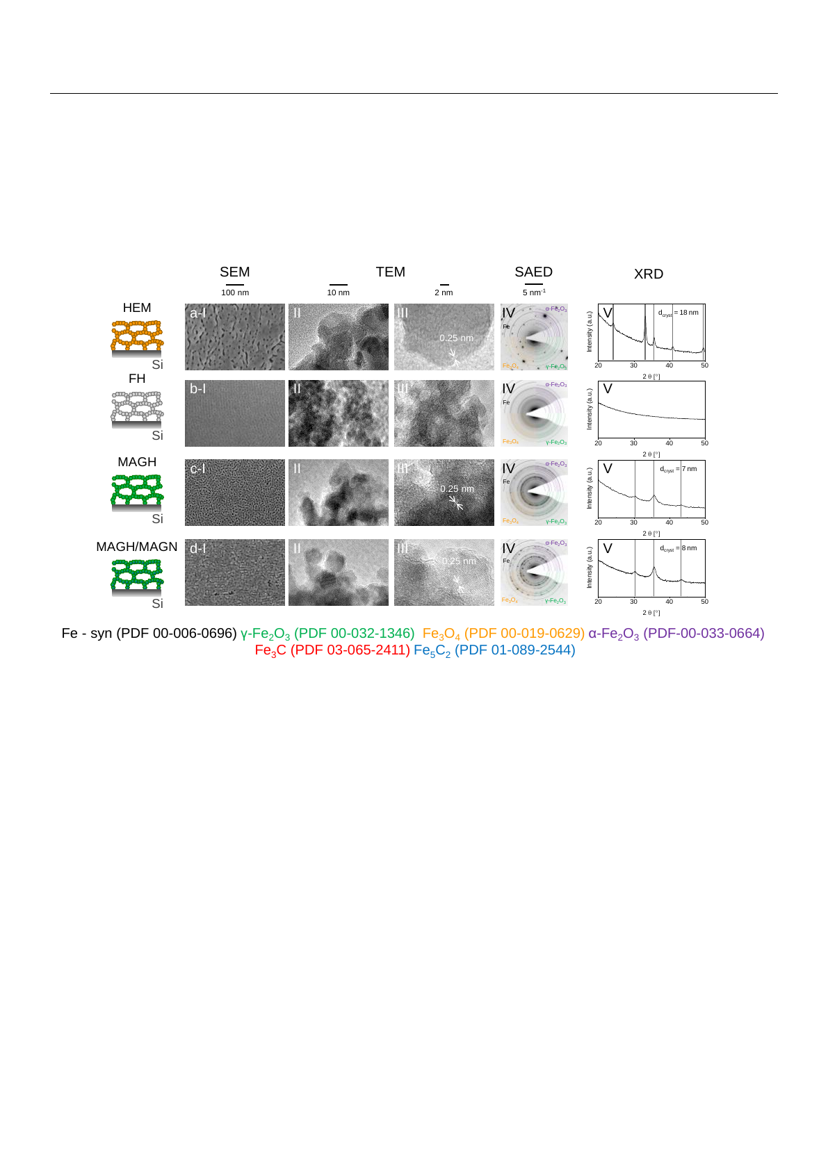
In order to study the formation of iron carbides during the aforementioned process,
scanning electron microscopy (SEM), transmission electron microscopy (TEM), and se-
lected area electron diffraction (SAED) were performed and presented alongside results
from X–ray diffraction measurements in gracing–incidence geometry for the incoming
beam (GI–XRD) of the fresh hematite (HEM), ferrihydrite (FH), maghemite (MAGH), and
maghemite/magnetite (MAGH/MAGN) films are presented in Figure 1.
Catalysts 2021, 11, x FOR PEER REVIEW 4 of 11
In order to study the formation of iron carbides during the aforementioned process,
scanning electron microscopy (SEM), transmission electron microscopy (TEM), and se-
lected area electron diffraction (SAED) were performed and presented alongside results
from X–ray diffraction measurements in gracing–incidence geometry for the incoming
beam (GI–XRD) of the fresh hematite (HEM), ferrihydrite (FH), maghemite (MAGH), and
maghemite/magnetite (MAGH/MAGN) films are presented in Figure 1.
Figure 1. Fresh iron oxide films obtained after controlled exposure of the mesophase to different gas
atmospheres. 550 °C air for 10 min forms (a) HEM and 400 °C air for 10 min (b) FH. 350 °C in N2 for
5 h forms (c) MAGH. 400 °C in N2 for 2 h → 350 °C in H2/Ar for 1 h (d) MAGH/MAGN. All samples
were characterized by (I) SEM, (II/III) TEM, (IV) SAED and (V) GI−XRD.
Fresh hematite (HEM) samples (Figure 1a) present a mesoporous–templated film
with a grid–like morphology according to SEM imaging (Figure 1(aI)), which can be ex-
plained by sintering processes of neighboring crystallites. Such grid–like structures have
already been observed in our previous work [21] and for other systems (e.g., TiO2, Nb2O5)
[29,30]. Representative TEM images (Figure 1(aII,III)) reveal partially sintered crystallites
and an average pore wall thickness of 11 ± 3 nm. Compared to the SEM top view images
the pore walls appear to be thinner in the bulk indicating a higher degree of sintering on
the surface. The recorded SAED pattern can be assigned to hematite (Figure 1(aIV)) and
shows only few spots instead of homogeneous diffraction rings observed for polycrystal-
line materials. These patterns have been recorded for spots larger than 100 nm, indicating
crystallites sharing a nearly identical orientation [30]. The GI–XRD pattern (Figure 1(aV))
shows narrow reflections for a pure hematite phase and crystallite size of 18 nm deter-
mined using the Debye–Scherrer equation for the strongest reflection at 2θ = 33.153°.
Ferrihydrite (FH) precursor films are fine–grained, low crystalline materials with a
well–ordered mesoporosity (SEM Figure 1(bI)). The absence of any clear lattice fringes in
the corresponding TEM images confirms a low crystallinity (Figure 1(bII,III)), which is
further corroborated by SAED analysis (Figure 1(bIV)). Evidently, the SAED pattern only
shows signals stemming from the carbon film of the TEM grid. The formation of larger
crystallites was ruled out using GI–XRD analysis (Figure 1(bV)).
Maghemite (MAGH) precursor films feature a well–defined pore structure with a
pore diameter of 7 ± 1 nm (Figure 1(cI)). Lattice fringes observed in representative TEM
images can be assigned to the maghemite phase and the pore walls have an average thick-
ness of 7 ± 1 nm (Figure 1(cII,III)). Several rings can be observed in the SAED pattern,
which can be assigned to maghemite (Figure 1(cIV)). The GI–XRD pattern (Figure 1(cV))
20 30 40 50
Intensity (a.u.)
2 q [°]
100 nm
SEM SAEDTEM
10 nm
0.25 nm
0.25 nm
0.25 nm
2nm
Fe
5nm-1
α-Fe2O3
Fe3O4γ-Fe2O3
Fe
α-Fe2O3
Fe3O4γ-Fe2O3
Fe
α-Fe2O3
Fe3O4γ-Fe2O3
Fe
α-Fe2O3
Fe3O4γ-Fe2O3
Si
Si
MAGH
Si
MAGH/MAGN
Si
FH
HEM
20 30 40 50
Intensity (a.u.)
2 q [°]
20 30 40 50
Intensity (a.u.)
2 q [°]
20 30 40 50
Intensity (a.u.)
2 q [°]
a-I II III IV
b-I II III IV
c-I II III IV
d-I II III IV
V
V
V
V
Fe - syn (PDF 00-006-0696) γ-Fe2O3(PDF 00-032-1346) Fe3O4(PDF 00-019-0629) α-Fe2O3(PDF-00-033-0664)
Fe3C (PDF 03-065-2411) Fe5C2(PDF 01-089-2544)
XRD
dcryst =18nm
dcryst = 7nm
dcryst = 8nm
Figure 1.
Fresh iron oxide films obtained after controlled exposure of the mesophase to different gas atmospheres. 550
◦
C
air for 10 min forms (
a
) HEM and 400
◦
C air for 10 min (
b
) FH. 350
◦
C in N
2
for 5 h forms (
c
) MAGH. 400
◦
C in N
2
for 2 h
→
350
◦
C in H
2
/Ar for 1 h (
d
) MAGH/MAGN. All samples were characterized by (I) SEM, (II/III) TEM, (IV) SAED and
(V) GI−XRD.
Fresh hematite (HEM) samples (Figure 1a) present a mesoporous–templated film with
a grid–like morphology according to SEM imaging (Figure 1(aI)), which can be explained
by sintering processes of neighboring crystallites. Such grid–like structures have already
been observed in our previous work [
21
] and for other systems (e.g., TiO
2
, Nb
2
O
5
) [
29
,
30
].
Representative TEM images (Figure 1(aII,III)) reveal partially sintered crystallites and an
average pore wall thickness of 11
±
3 nm. Compared to the SEM top view images the pore
walls appear to be thinner in the bulk indicating a higher degree of sintering on the surface.
The recorded SAED pattern can be assigned to hematite (Figure 1(aIV)) and shows only
few spots instead of homogeneous diffraction rings observed for polycrystalline materials.
These patterns have been recorded for spots larger than 100 nm, indicating crystallites
sharing a nearly identical orientation [
30
]. The GI–XRD pattern (Figure 1(aV)) shows
narrow reflections for a pure hematite phase and crystallite size of 18 nm determined using
the Debye–Scherrer equation for the strongest reflection at 2θ= 33.153◦.
Ferrihydrite (FH) precursor films are fine–grained, low crystalline materials with a
well–ordered mesoporosity (SEM Figure 1(bI)). The absence of any clear lattice fringes in
the corresponding TEM images confirms a low crystallinity (Figure 1(bII,III)), which is
further corroborated by SAED analysis (Figure 1(bIV)). Evidently, the SAED pattern only
shows signals stemming from the carbon film of the TEM grid. The formation of larger
crystallites was ruled out using GI–XRD analysis (Figure 1(bV)).
Catalysts 2021,11, 773 5 of 11
Maghemite (MAGH) precursor films feature a well–defined pore structure with a pore
diameter of 7
±
1 nm (Figure 1(cI)). Lattice fringes observed in representative TEM images
can be assigned to the maghemite phase and the pore walls have an average thickness of
7±1 nm
(Figure 1(cII,III)). Several rings can be observed in the SAED pattern, which can
be assigned to maghemite (Figure 1(cIV)). The GI–XRD pattern (Figure 1(cV)) recorded
for maghemite features reflections corresponding to either maghemite or magnetite. Due
to the structural similarity of maghemite and magnetite, it is not possible to distinguish
between both crystal phases. Using the Scherrer equation for the strongest reflection at 2
θ
= 35.7
◦
, an average crystallite size of 7 nm was determined which correspond well to the
wall thickness determined by TEM.
Maghemite films that have been partially transformed into magnetite by reductive
treatment (MAGH/MAGN) show signs of grain coarsening and the formation of a grid–
like structure (Figure 1(dI)). SAED (Figure 1(dV)) and GI–XRD (Figure 1(dV)) results are
similar to the MAGH film. As mentioned above, it is not possible to clearly assign the
maghemite or magnetite phase. With 8 nm, a similar value for the average crystallite size
can be obtained.
In general, the properties of all precursor films are consistent with results from previ-
ously reported studies [19–21].
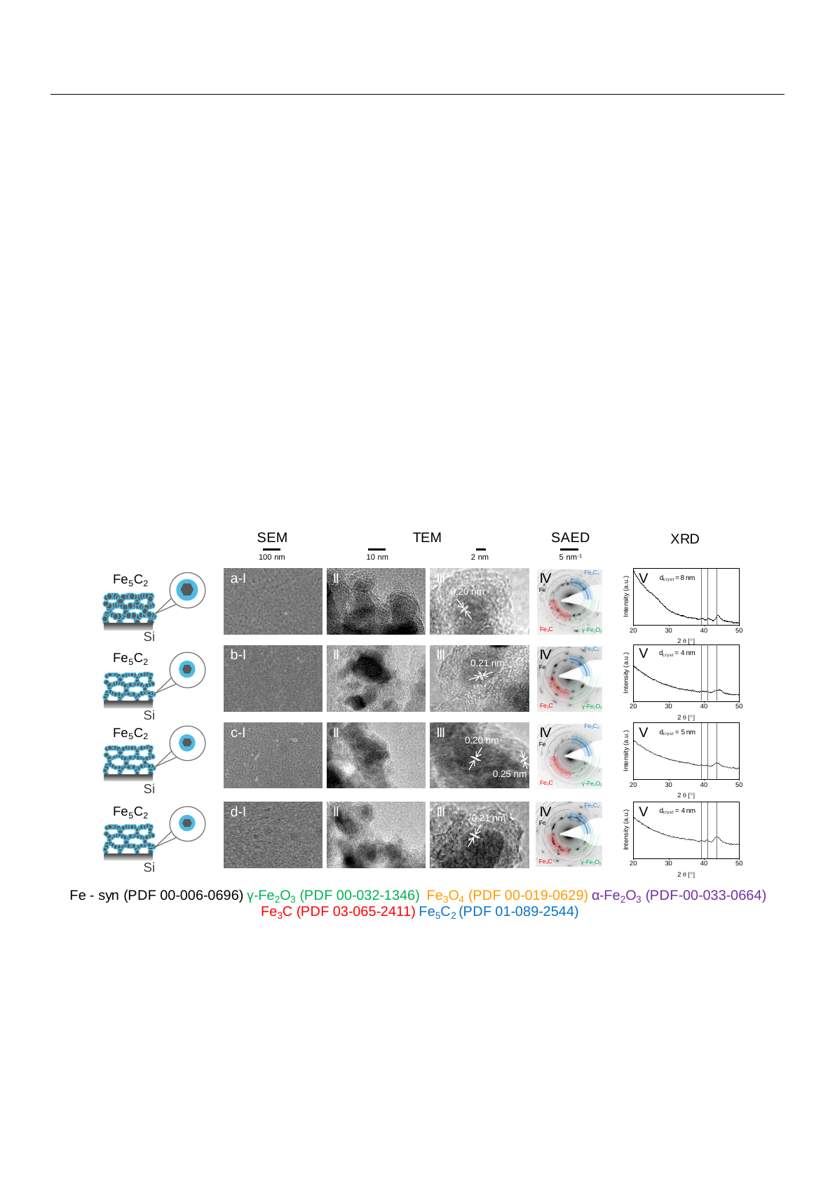
In order to study the precursor films’ tendencies to form carbides, all iron oxide films
were treated in CO/H
2
at 300
◦
C for 20 h. Figure 2displays the corresponding (I) SEM, (II,
III) TEM, (IV) SAED, and (V) GI–XRD analysis results.
Catalysts 2021, 11, x FOR PEER REVIEW 5 of 11
recorded for maghemite features reflections corresponding to either maghemite or mag-
netite. Due to the structural similarity of maghemite and magnetite, it is not possible to
distinguish between both crystal phases. Using the Scherrer equation for the strongest
reflection at 2θ = 35.7°, an average crystallite size of 7 nm was determined which corre-
spond well to the wall thickness determined by TEM.
Maghemite films that have been partially transformed into magnetite by reductive
treatment (MAGH/MAGN) show signs of grain coarsening and the formation of a grid–
like structure (Figure 1(dI)). SAED (Figure 1(dV)) and GI–XRD (Figure 1(dV)) results are
similar to the MAGH film. As mentioned above, it is not possible to clearly assign the
maghemite or magnetite phase. With 8 nm, a similar value for the average crystallite size
can be obtained.
In general, the properties of all precursor films are consistent with results from pre-
viously reported studies [19–21].
In order to study the precursor films’ tendencies to form carbides, all iron oxide films
were treated in CO/H2 at 300 °C for 20 h. Figure 2 displays the corresponding (I) SEM, (II,
III) TEM, (IV) SAED, and (V) GI–XRD analysis results.
Figure 2. Physicochemical analysis for mesoporous iron oxide films after treatment in CO/H2 (2 to
1) flowrate 372 mL/min at 300 °C for 20 h. (a) HEM, (b) FH, (c) MAGH, and (d) MAGH/MAGN. All
samples were characterized by (I) SEM, (II/III) TEM, (IV) SAED, and (V) GI–XRD.
HEM precursor films show well–preserved mesopores after the treatment, as evi-
denced by top–view SEM imaging (Figure 2(aI)). Yet, there are indications for a swelling
of the pore walls. TEM images (Figure 2(aII,III)) illustrate the formation of a core–shell
structure of the carburized materials. Lattice fringes of 0.20 nm matching to (510) lattice
planes of Fe5C2 can be observed in the core indicating the full transformation of the initial
hematite to a carbide phase. The shell appears to consist of a low–crystallinity material
with no lattice fringes. Diffraction spots in the SAED pattern (Figure 2(aIV)) are also con-
sistent with the formation of iron carbides. However, assignment of carbides is challeng-
ing due to the great number of possible diffraction rings. The GI–XRD pattern (Figure
2(aV)) features three reflections that nicely match to reflections of Fe5C2. An average crys-
tallite size of 8 nm can be determined, indicating a significant decrease in crystallite size
compared to the corresponding oxide phase.
FH precursor films treated in CO/H2 feature a grid–like structure (SEM, Figure 2(bI)).
Similar to HEM, the analysis via TEM imaging indicates a core–shell structure consisting
of a crystalline carbide core (lattice fringes of 0.21 nm corresponding to (021) lattice planes)
20 30 40 50
Intensity (a.u.)
2 q [°]
20 30 40 50
Intensity (a.u.)
2 q [°]
20 30 40 50
Intensity (a.u.)
2 q [°]
20 30 40 50
Intensity (a.u.)
2 q [°]
0.21 nm
0.20 nm
10 nm100 nm
SEM SAEDTEM
2nm
0.20 nm
5nm-1
Fe - syn (PDF 00-006-0696) γ-Fe2O3(PDF 00-032-1346) Fe3O4(PDF 00-019-0629) α-Fe2O3(PDF-00-033-0664)
Fe3C (PDF 03-065-2411) Fe5C2(PDF 01-089-2544)
0.21 nm
0.25 nm
Fe
Fe5C2
Fe3Cγ-Fe2O3
Fe
Fe5C2
Fe3Cγ-Fe2O3
Fe
Fe5C2
Fe3Cγ-Fe2O3
Fe
Fe5C2
Fe3Cγ-Fe2O3
V
V
V
V
XRD
a-I II III IV
b-I II III IV
c-I II III IV
d-I II III IV
Si
Fe5C2
Si
Fe5C2
Si
Fe5C2
Si
Fe5C2
dcryst =8 nm
dcryst = 5nm
dcryst = 4nm
dcryst = 4 nm
Figure 2.
Physicochemical analysis for mesoporous iron oxide films after treatment in CO/H
2
(2 to 1) flowrate 372 mL/min
at 300
◦
C for 20 h. (
a
) HEM, (
b
) FH, (
c
) MAGH, and (
d
) MAGH/MAGN. All samples were characterized by (I) SEM, (II/III)
TEM, (IV) SAED, and (V) GI–XRD.
HEM precursor films show well–preserved mesopores after the treatment, as evi-
denced by top–view SEM imaging (Figure 2(aI)). Yet, there are indications for a swelling
of the pore walls. TEM images (Figure 2(aII,III)) illustrate the formation of a core–shell
structure of the carburized materials. Lattice fringes of 0.20 nm matching to (510) lattice
planes of Fe
5
C
2
can be observed in the core indicating the full transformation of the initial
Loading more pages...