
METAL ADDITIVE MANUFACTURING
In situ microstructure analysis of Inconel 625
during laser powder bed fusion
Felix Schmeiser
1,
* , Erwin Krohmer
2
, Christian Wagner
1
, Norbert Schell
3
, Eckart Uhlmann
2,4
, and
Walter Reimers
1
1
Institute for Materials Science and Technology, Metallic Materials, Technische Universität Berlin, Ernst Reuter Platz 1, 10587 Berlin,
Germany
2
Institute for Machine Tools and Factory Management (IWF), Technische Universität Berlin, Pascalstraße 8-9, 10587 Berlin,
Germany
3
Helmholtz-Zentrum Hereon, Max-Planck-Str. 1, 21502 Geesthacht, Germany
4
Fraunhofer Institute for Production Systems and Design Technology (IPK), Pascalstraße 8-9, 10587 Berlin, Germany
Received: 1 July 2021
Accepted: 29 September 2021
Published online:
8 November 2021
ÓThe Author(s) 2021
ABSTRACT
Laser powder bed fusion is an additive manufacturing process that employs
highly focused laser radiation for selective melting of a metal powder bed. This
process entails a complex heat flow and thermal management that results in
characteristic, often highly textured microstructures, which lead to mechanical
anisotropy. In this study, high-energy X-ray diffraction experiments were car-
ried out to illuminate the formation and evolution of microstructural features
during LPBF. The nickel-base alloy Inconel 625 was used for in situ experiments
using a custom LPBF system designed for these investigations. The diffraction
patterns yielded results regarding texture, lattice defects, recrystallization, and
chemical segregation. A combination of high laser power and scanning speed
results in a strong preferred crystallographic orientation, while low laser power
and scanning speed showed no clear texture. The observation of a constant
gauge volume revealed solid-state texture changes without remelting. They
were related to in situ recrystallization processes caused by the repeated laser
scanning. After recrystallization, the formation and growth of segregations were
deduced from an increasing diffraction peak asymmetry and confirmed by ex
situ scanning transmission electron microscopy.
Handling Editor: Sophie Primig.
https://doi.org/10.1007/s10853-021-06577-8
J Mater Sci (2022) 57:9663–9677
Metal Additive Manufacturing
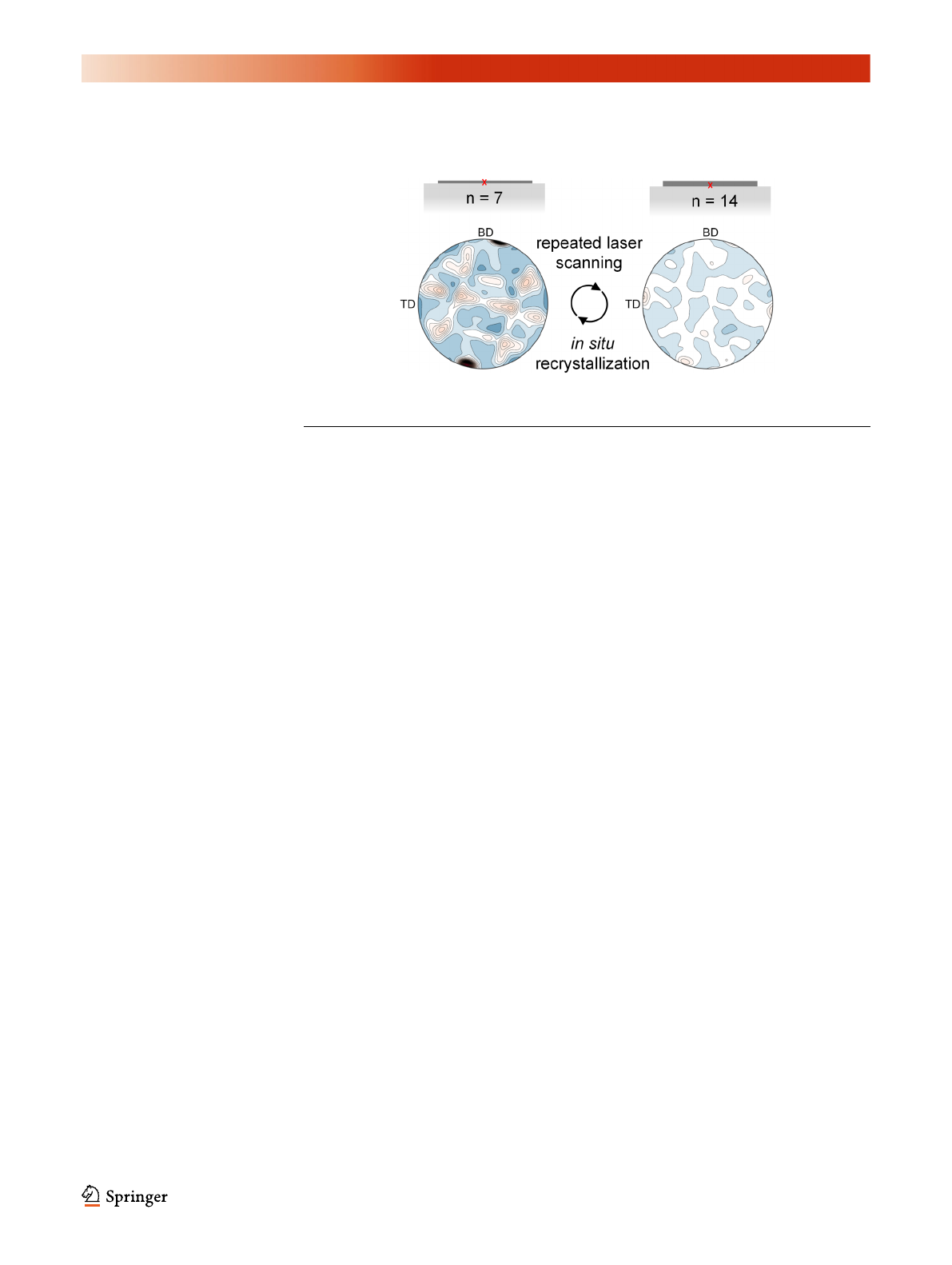
GRAPHICAL ABSTRACT
Introduction
Additive manufacturing facilitates the fabrication of
arbitrarily complex geometries and tailored material
properties using a range of different materials. Laser
powder bed fusion (LPBF) is a process especially suited
for the production of metal parts. LPBF employs focused
laser radiation to melt a powder bed selectively. After
laser exposure, the material solidifies immediately, and a
new powder layer is applied, resulting in the layer-wise
fabrication of the desired geometry. The selective and
both locally and temporally varying energy input leads to
a complex heat flow and temperature distribution, which
govern the solidification and grain growth regime. Pre-
cise knowledge of the interaction of laser parameters and
microstructural response within the workpiece opens up
the prospect of tailored microstructure design.
Several properties characterize the microstructure
of crystalline material, e.g., phase composition,
microscopic defects such as porosity, and nanoscopic
crystal lattice defects. Additionally, the grains’ size,
morphology, and crystallographic orientation
severely impact the material’s mechanical properties.
The entirety of all crystallographic orientations in a
polycrystalline material is summarized as its texture.
The texture is often described as the deviation from
a random orientation distribution. The texture of a
polycrystal is created during processes that define the
microstructure, such as solidification and crystal-
lization of a molten mass, recrystallization, and
plastic deformation. The texture is determined by
factors with a directed impact, such as mechanical
force in plastic deformation or a directed heat flow
during solidification [1].
A textured material exhibits anisotropic properties,
e.g., Young’s modulus, ductility, strength, and hard-
ness. In LPBF, the directed solidification initially
determines the texture as the material is exposed
with a focused laser beam. The grain growth and the
texture in a LPBF manufactured specimen are influ-
enced by the melt pool geometry and the thermal
gradients acting in the component [2]. As the melt
pool solidifies, grains nucleate at the solidification
front. During the subsequent grain growth, grains
with different orientations compete [3]. Several
studies found that grains with an orientation parallel
to the melt pool boundary normal dominate during
this phase [2,4–6]. This preferred orientation results
from the heat flow, which has its largest magnitude
in the melt pool boundary’s normal direction [7]. The
preferred orientation is, furthermore, dependent on
the crystal lattice. For example, face-centered
cubic (fcc) metals such as the nickel-base alloy
Inconel 625 grow in the preferred h100idirection [1].
The melt pool geometry depends on several fac-
tors, e.g., thermal conductivity, energy absorption,
and heat flow [6,8]. Gong et al. [9] investigated the
influence of different laser powers and scanning
speeds on the melt pool geometry. They found that
high laser powers and low scanning speeds lead to
the keyhole effect. Here, the melt pool shows a broad
opening at the top and tapers toward the bottom. The
keyhole has a high penetration depth due to the high
laser intensity and energy input, resulting in the
remelting of previously solidified material.
9664 J Mater Sci (2022) 57:9663–9677

Furthermore, keyholing leads to undesirable
porosity [10]. Contrarily, a combination of low laser
power and high scanning speeds leads to the balling
effect. If the energy input is insufficient, the layer
below will be insufficiently wetted. Spherical melt
pools and bead-like structures are formed, which
impede the following layers and can disrupt the
manufacturing process by jamming the powder
recoating mechanism [11].
The energy input also impacts grain growth.
Higher laser powers lead to deeper melt pools, lower
laser powers to shallower melt pools. In shallower
melt pools, the normal vectors on the melt pool
boundaries are more parallel than in deeper melt
pools. They are parallel to the building direction of
the part, therefore resulting in a preferred orientation
in the building direction [6]. The melt pools are
deeper when using lower scanning speeds or high
laser powers, leading to a more significant variation
of the melt pool boundary normal directions [4].
Therefore, crystallites do not only grow in the
building direction, resulting in a lower preferred
orientation [6]. Sun et al. [4] concluded that texture
development could be controlled via process control.
They successfully built parts from 316L, which
showed a h011ifiber texture instead of the commonly
found h001ifor fcc alloys by using an increased laser
power and a multi-scan method.
Yin et al. [5] found a dependence between the
orientation of grain growth and laser power and
scanning speed using FEM simulations for Ti-6Al-V4
processed via LPBF. They concluded that the layer
number exerts an influence on the melt pool geome-
try and, therefore, on the grain orientation. For small
layer numbers, the substrate plate strongly influences
heat dissipation. Here, the crystal orientations show
substantial deviations from the building direction.
With increasing layer numbers, the melt pool
becomes shallower, and the grain growth changes
toward the building direction after a few layers. [5]
Several approaches to tailor the microstructure via
process parameter manipulation have been published
to date. Roehling et al. [12] adjusted the shape of the
laser beam to generate preferable microstructures and
mechanical properties. Dehoff et al. [13] showed that
tailored, site-specific textures could be designed by
varying the process parameters. The typical route is a
post-process heat treatment, usually aimed at achieving
a recrystallized microstructure [14]. For Inconel 625,
Marchese et al. [15] investigated the microstructural
evolution after various heat treatments and found a
recrystallized microstructure after a solution heat
treatment. Sabzi et al. [16] recently presented the first
experimental proof that dynamic recrystalliza-
tion (DRX) occurs during LPBF as well, using ex situ
EBSD measurements and thermomechanical modeling.
However, an in situ observation of DRX during LPBF
has not been reported yet.
Since DRX impacts the crystallographic texture,
high-energy synchrotron radiation diffraction is well-
suited for its investigation. In situ diffraction experi-
ments so far have been focused on phase transfor-
mations [17], cooling dynamics [18,19], and internal
stresses [20,21]. Recently, Wahlmann et al. [22]
presented results regarding the in situ formation of
precipitates, another important constituent of the
microstructure, in a nickel-base superalloy using
synchrotron radiation diffraction and the LPBF
device from the present study’s group.
To the authors’ knowledge, for LPBF, in situ tex-
ture analyses using high-energy synchrotron radia-
tion have not been reported so far. Using a custom-
built LPBF machine designed for in situ diffraction
measurements, experiments using Inconel 625 were
carried out to determine the development of texture
and the influence of repeated laser scanning on the
microstructure.
Materials and methods
Custom LPBF machine
In previous work, a custom LPBF process chamber
was developed and integrated into the modular LPBF
machine AconityMINI from Aconity3D GmbH, Her-
zogenrath, Germany, to realize in situ X-ray diffrac-
tion experiments with synchrotron radiation [23].
The custom LPBF machine is equipped with a 400 W
Ytterbium fiber laser YLR-400-AC from IPG La-
ser GmbH, Burbach, Germany. The laser source
emits light with a wavelength of 1070 nm in contin-
uous wave. The laser is focused and deflected on the
powder bed with an Axialscan-30 from Ray-
lase GmbH, Wessling, Germany, with a focus diam-
eter of ca. 60 lm in 1/e
2
specification. Before
processing, the process chamber was sealed and
purged with argon. During the processing, a clean
argon atmosphere was maintained by using a filtra-
tion unit connected to the process chamber and
J Mater Sci (2022) 57:9663–9677 9665
coupled to a circulation pump. The powder bed was
sandwiched between two glassy carbon windows.
Inlet and outlet windows for the synchrotron radia-
tion in the process chamber are made from polyimide
foil. An automatic powder recoating mechanism
inside the purged process chamber ensured the
additive manufacturing of multi-layer parts without
interrupting the experiment for manual operations.
Materials
The nickel-base alloy 625, commonly referred to as
Inconel 625, was used as powder material and pur-
chased from m4p material solutions GmbH, Magde-
burg, Germany. The particles were nitrogen-
atomized and exhibited mostly spherical shapes,
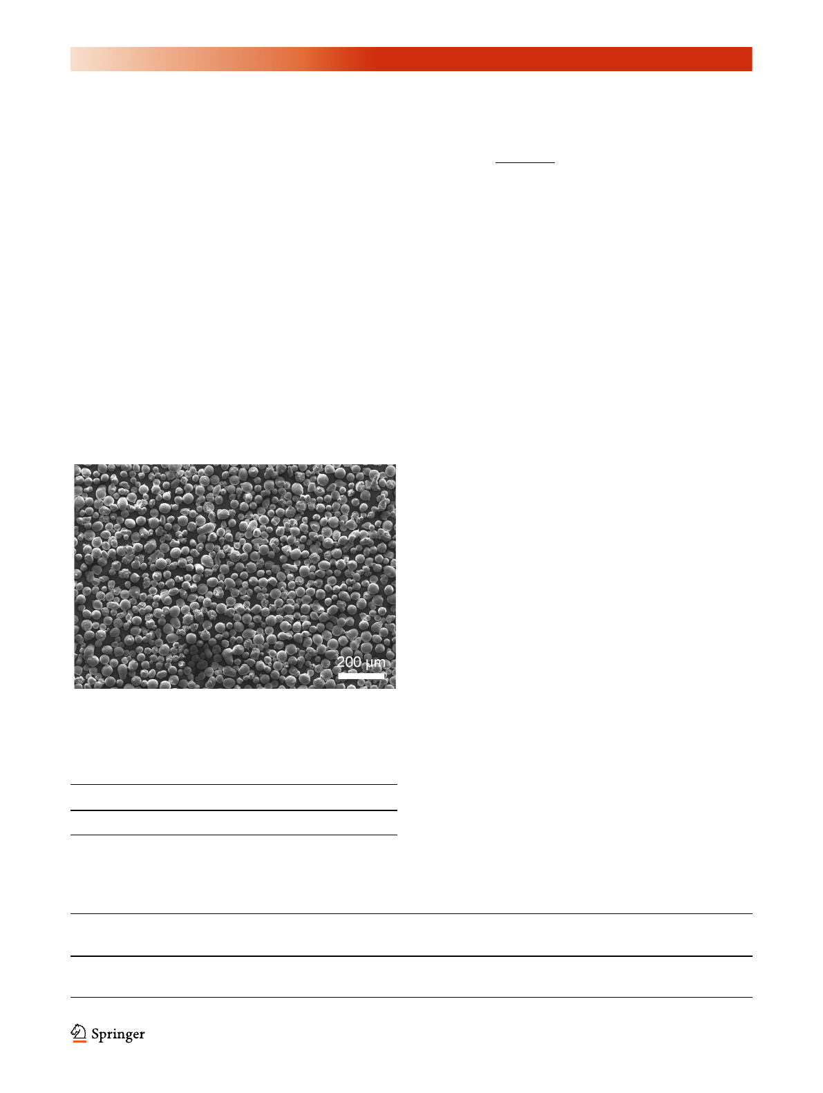
Fig. 1, with particle sizes ranging from 20 lmto
63 lm, Table 1. The median circularity of the
particles, calculated with Eq. 1, was 0.85 with circ = 1
equaling a perfect circle.
circ ¼4pArea
Perimeter2;ð1Þ
Structural steel S235 plates with a size of 70 9
20 93mm
3
were used as substrate material.
Process parameters and measurement modes
Two different LPBF parameter sets were investigated,
Table 2. They are composed of two pairs of laser
power P
L
and scanning speed v
L
ranging from a low
laser power P
L
= 55 W and low scanning speed
v
L
= 50 mm/s to a high laser power P
L
= 275 W and
a high scanning speed v
L
= 760 mm/s. The ratio of
laser power P
L
to scanning speed v
L
is denoted as
line energy E
L
. The scanning pattern featured unidi-
rectional scanning vectors aligned longitudinally to
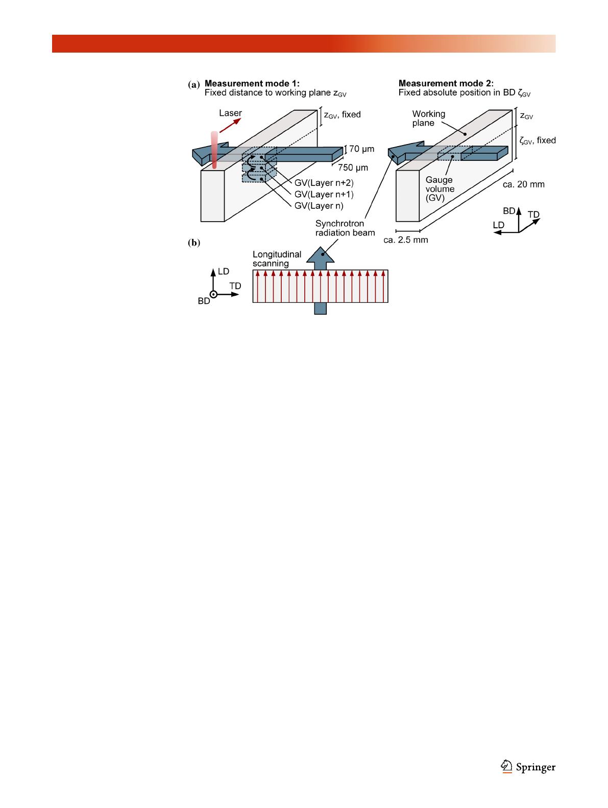
the incident synchrotron radiation beam, Fig. 2.
Cuboid samples ca. 20 92.5 95mm
3
in size were
produced out of 100 layers with a layer thickness of
Dz=50lm. Laser scanning was set to start at the left
edge and finish at the right edge of the sample
geometry. Two different measurement modes were
used. In measurement mode 1 (MM1), the gauge
volume (GV) distance to the working plane, z
GV
,is
kept constant throughout the measurement of all the
100 layers. In measurement mode 2 (MM2), the
absolute gauge volume position in the sample is
maintained such that a defined volume element of
the sample, defined by its distance to the sample-
substrate interface, f
GV
, is tracked throughout the
process.
In this study, the axis parallel to the incident syn-
chrotron radiation beam is called longitudinal direc-
tion (LD), which spans the working plane together
with the transverse direction (TD). The third axis is
parallel to the part height and called the building
direction (BD).
Table 1 Particle size distribution of Inconel 625 powder per sieve
analysis
0–20 lm 20–40 lm 40–50 lm 50–63 lm?63 lm
0.68% 67.64% 29.42% 2.26% 0.0%
Table 2 Parameter sets for the experiments
Parameter
unit
Laser power P
L
[W]
Scanning speed v
L
[mm/s]
Line energy E
L
[J/mm]
Scanning pattern Hatch distance h
L
[lm]
Layer thickness Dz
[lm]
Set 1 55 50 1.1 Longitudinal 120 50
Set 2 275 760 0.36
Figure 1 SEM image of Inconel 625 powder.
9666 J Mater Sci (2022) 57:9663–9677
Experimental procedure
In situ diffraction experiments were carried out at
PETRA III, Deutsches Elektronen-Synchrotron (DESY)
in Hamburg, Germany. The High Energy Materials
Science (HEMS) beamline P07 [24], which is operated
by Helmholtz-Zentrum Hereon, features a heavy load
6-axis positioning system on which the process
chamber of the custom LPBF machine was mounted.
A PerkinElmer XRD1621 area detector was used for
diffraction pattern acquisition. For the diffraction
experiments, synchrotron radiation energies of 87
and 98 keV were used. The synchrotron radiation
beam size was set to 750 lm in TD and 70 lminBD,
Fig. 2.
The diffraction patterns were acquired with an
exposure time t = 0.1 s and frequency f = 10 Hz.
Patterns were collected as layer-wise image series
when the laser emission was active. The series mea-
surement started with the laser being turned on and
ended at the end of laser scanning. Therefore, not the
whole cooling process after the laser impact was
observed.
To complement the in situ diffraction experiments,
two specimens were analyzed after production using
standard metallographic preparation methods. For
both parameter sets, the TD-BD plane was polished
and etched in a solution of 1.5 ml hydrogen peroxide
and 50 ml hydrochloric acid for t = 45 s. This
preparation emphasized grain structures and melt
pool boundaries in the subsequent optical micro-
scopy using a Zeiss Axioskop 50.
Additionally, one sample, manufactured using
P
L
= 55 W, was investigated by scanning transmis-
sion electron microscopy (STEM) at Zentraleinrich-
tung Elektronenmikroskopie (ZELMI) of Technische
Universita
¨t Berlin. The specimen was cut using a
focused ion beam on a FEI Helios Nanolab 600 FIB to
ensure that the subsequent STEM analysis probed the
same gauge volume as the in situ diffraction experi-
ments in MM2. The investigations were carried out
using a JEOL JEM-ARM300F2 STEM with a cold field
emission gun and a probe-Cs corrector operating at
an acceleration voltage of 300 kV and equipped with
a JEOL Dual-EDX system using two 160 mm
2
SDD
detectors. High-angular annular dark-field images
(HAADF) were acquired because of their high sen-
sitivity to the atomic number of the probed material.
Data evaluation
The detector calibration and integration were per-
formed using the Python library pyFAI [25], pole
figures were generated using MTEX [26]. The detec-
tor calibration was performed using a standard LaB6
powder sample to determine the detector-sample
distance and the detector tilt for accurate integration
results. Subsequently, the diffraction patterns were
integrated in 5°sectors, resulting in 72 line profiles,
including the first five hkl reflections for each
Figure 2 Experimental
procedure: aMeasurement
modes and gauge volume
positioning; bLaser scanning
pattern.
J Mater Sci (2022) 57:9663–9677 9667
Loading more pages...