
Aeroelastic assessment of a highly loaded high pressure
compressor exposed to pressure gain combustion
disturbances
Victor Bicalho Civinelli de Almeida
1,*
, Dieter Peitsch
1
1
Technical University of Berlin, Marchstr. 12-14, Berlin 10587, BE, Germany
Abstract
A numerical aeroelastic assessment of a highly loaded high pressure com-
pressor exposed to flow disturbances is presented in this paper. The distur-
bances originate from novel, inherently unsteady, pressure gain combustion
processes, such as pulse detonation, shockless explosion, wave rotor or
piston topping composite cycles. All these arrangements promise to reduce
substantially the specific fuel consumption of present-day aeronautical
engines and stationary gas turbines. However, their unsteady behavior must
be further investigated to ensure the thermodynamic efficiency gain is not
hindered by stage performance losses. Furthermore, blade excessive vibra-
tion (leading to high cycle fatigue) must be avoided, especially under the
additional excitations frequencies from waves traveling upstream of the
combustor.
Two main numerical analyses are presented, contrasting undisturbed with
disturbed operation of a typical industrial core compressor. The first part of
the paper evaluates performance parameters for a representative blisk stage
with high-accuracy 3D unsteady Reynolds-averaged Navier-Stokes compu-
tations. Isentropic efficiency as well as pressure and temperature unsteady
damping are determined for a broad range of disturbances. The nonlinear
harmonic balance method is used to determine the aerodynamic damping.
The second part provides the aeroelastic harmonic forced response of the
rotor blades, with aerodynamic damping and forcing obtained from the
unsteady calculations in the first part. The influence of blade mode shapes,
nodal diameters and forcing frequency matching is also examined.
Introduction
Increase in overall efficiency of aeronautical engines and stationary gas
turbines, reducing specific fuel consumption, is being extensively
researched. Since traditional engine configurations are reaching saturation
development state, novel technological breakthroughs are sought. Among
these radical changes, the most significant tackle either the core/bypass
flows or the combustor losses. To address core flow hurdles, intercool-
ing, Rankine bottoming and recuperation might be viable options.
Reheating is also particularly developed for land-based applications.
Concerning bypass losses, geared turbofan and open rotor concepts are
receiving considerable attention (Grönstedt et al., 2013,2016;Gülen,
2017).
With respect to the combustion losses, several innovative approaches
have been proposed. Most of them aim at improving current constant-
pressure (in fact, pressure-loss) combustion with a pressure-increase
process. This so-called pressure gain combustion (PGC) can be
Original article
Article history:
Accepted: 16 July 2018
Published: 15 October 2018
This paper was originally presented at the
GPPS Montreal 18 Conference, in Montreal,
May 7–9 2018.
*Correspondence:
VB: [email protected]-berlin.de
Peer review:
Single blind
Copyright:
© 2018 Bicalho Civinelli de Almeida and
Peitsch This is an open access article
distributed under the Creative Commons
Attribution Non Commercial No Derivatives
License (CC BY-NC-ND 4.0). Unrestricted
use, distribution, and reproduction of the
original work are permitted for
noncommercial purposes only, provided it
is properly cited and its authors credited.
No derivative of this work may be
distributed.
Keywords:
aeroelasticity; forced response; unsteady
performance; axial compressor; high
pressure compressor; pressure gain
combustion
Citation:
Bicalho Civinelli de Almeida V., Peitsch D.
(2018). Aeroelastic assessment of a highly
loaded high pressure compressor exposed
to pressure gain combustion disturbances.
Journal of the Global Power and Propulsion
Society. 2: 477–492.
https://doi.org/10.22261/JGPPS.F72OUU
J. Glob. Power Propuls. Soc. | 2018 | 2: 477–492 | https://doi.org/10.22261/JGPPS.F72OUU 477
JOURNAL OF THE GLOBAL POWER AND PROPULSION SOCIETY
journal.gpps.global/jgpps

accomplished by different means. The leading paths are pulse detonation (Roy et al., 2004;Pandey and
Debnath, 2016), rotating detonation (Zhou et al., 2016;Kailasanath, 2017;Paxson and Naples, 2017), wave
rotors (Akbari and Nalim, 2009;McClearn et al., 2016) and shockless explosion (Bobusch et al., 2014;Reichel
et al., 2016) combustion. Some other concepts are the piston topping (Kaiser et al., 2015) and the nutating disk
(Meitner et al., 2006). All these setups are theoretically supported by substantial thermodynamic gains, described
in detail, e.g., by (Heiser and Pratt, 2002;Gray et al., 2016).
Despite fairly different construction and engine-integration characteristics, all these PGC processes introduce
additional unsteadiness into the adjacent turbomachinery components, namely, the compressor upstream and the
turbine downstream. This unsteadiness is directly linked with the inherently periodic nature of the combustion
mechanisms, and affect the operation of both stationary and rotating parts (traditionally designed by steady state
workflows). The integration between combustion units and engine (most likely through plena interfaces) is key
to estimate proper boundary conditions for the neighboring components, such as perturbation signatures, oper-
ation frequencies and amplitudes.
Although fundamental combustion research on pulse detonation had been restricted to low frequency pro-
cesses, massive increase in the number of ignitions per second has been achieved. Kilohertz pulse detonation
frequencies were recently reported by (Taki et al., 2017). As for rotating detonation, it already takes place in the
few kilohertz range (Lu and Braun, 2014;Bluemner et al., 2018). Similar periodicity is reported for the other
PGC devices. This frequency range is also expected to be pushed up, once PGC technology takes off.
With respect to the amplitudes of such disturbances, they are strongly linked to the PGC operation (such as
filling, ignition and purging phases), but also to the plena interfaces. Limited PGC experimental data with
upstream measurements is available, such as (Roy et al., 2004;Rasheed et al., 2005). Some numerical work used
pressure amplitude values at the combustor interfaces of a few percent up to approximately 40% (Van Zante
et al., 2007;Fernelius, 2017;Liu et al., 2017). This disturbance amplitude range is already significant from the
turbomachinery point of view, justifying detailed investigations.
The need for assessing the performance and aeroelasticity effects of these disturbances has been recognized by
the combustion and turbomachinery academic community (Kailasanath, 2003;Roy et al., 2004;Rasheed et al.,
2009;Lu and Braun, 2014;Gülen, 2017). However, quantitative information to evaluate the extent of these
changes is scarce, especially for state-of-the-art industrial machines. Up to the current date, there has been no full
integration between those PGC cores to commercial engines. Therefore, the current exploratory research sheds
some light into the effects of this interfacing (specifically upstream), by numerical means. Both performance and
aeroelasticity assessments will be presented.
The manuscript is organized as follows. In the case description section, the simulated high pressure compressor
geometry is characterized. Next, the numerical methodologies both for the computational fluid dynamics (CFD)
and computational solid mechanics (CSM) are presented. Subsequently, results are given for a broad range of dis-
turbance amplitudes and frequencies, followed by the main outcomes.
Case description
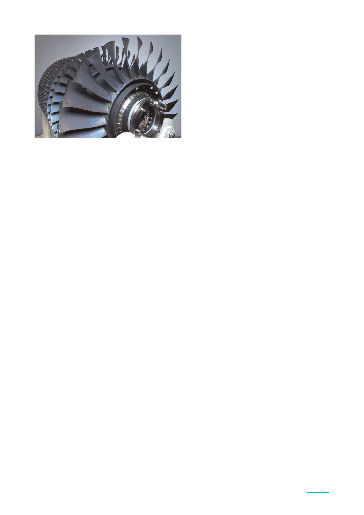
A modern industrial high pressure compressor, depicted in Figure 1 is here used for the simulations (Klinger et al.,
2008,2011). Practical 3D geometries and operation points have been provided by an industrial partner. It is
important to say that the whole engine has been designed for traditional deflagration combustion, without specific
considerations for PGC and its effects on turbomachinery components. Therefore, the present study analyzes how
this traditional setup would potentially react to unsteady disturbances and depart from the reference design.
The simulated domain is the HPC 6th stage, the last with a bladed disk (blisk) design. Although it is not the
very last stage right before the combustion chamber, it has been chosen considering that blisk manufacturing
becomes increasingly more common in axial compressor design (Peitsch et al., 2005;Honisch et al., 2012;
Mayorca et al., 2012;Zhao et al., 2015). Due to confidentiality constraints, the speedline itself and some abso-
lute design quantities will not be disclosed here, but rather normalized values, enough for full comprehension
and comparative evaluations.
Numerical methodology
For brevity purposes, neither the fluid nor the solid domain state and constitutive equations will be derived here.
Rather, focus will be given to the interface treatment of necessary aeroelastic quantities, such as aerodynamic
work or pressure harmonics. The next sections describe respectively the CFD (steady and unsteady) and CSM
J. Glob. Power Propuls. Soc. | 2018 | 2: 477–492 | https://doi.org/10.22261/JGPPS.F72OUU 478
Bicalho Civinelli de Almeida and Peitsch | Aeroelastic assessment of a HPC exposed to PGC disturb https://journal.gpps.global/a/F72OUU
methodologies used along this work. The space and time independence studies for the grids are likewise
presented.
Computational fluid dynamics
Due to the unsteady behavior associated with the new combustion processes, 3D unsteady viscid fluid dynamics
simulations are employed, both in time and frequency domain. Time-domain calculations are here used to deter-
mine performance parameters, unsteady damping and blade surface pressure harmonics, to be later used in the
structural simulations. Frequency-domain runs determine the aerodynamic damping.
(i) Steady state: the Navier-Stokes equations are boundary-layer resolved with the finite volumes solver CFX®
(ANSYS Academic Research, Release 18.1), with air (ideal gas) as compressible medium. Fourth-order Rhie
& Chow smoothing is employed (Rhie and Chow, 1983), while Reynolds stresses are computed by the
two-equation Menter’s SST turbulence model (Menter, 1994). Since the simulated stage is located substan-
tially far from the engine inlet, the flow is safely assumed to be fully turbulent, so no transition models were
shown necessary. Double-precision, properly converged steady state solutions (with root-mean-square residuals
lower than 10
−5
, and imbalances lower than 5·10
−6
) are used as initial conditions for the unsteady runs.
The 3D geometries were meshed with AutoGrid5® developed by Numeca (IGG™/AutoGrid5™v11.1). Both
root fillet and tip gap have been modeled. Multi-block structured hexaedra meshes were employed, with direc-
tional boundary-layer refinement on all walls (dimensionless wall distance yþ1), keeping the expansion ratio
below 1.2. The topology for both rotor blades and stator vanes is the O4H. The tip gap was modeled with at
least 30 cells in the radial direction.
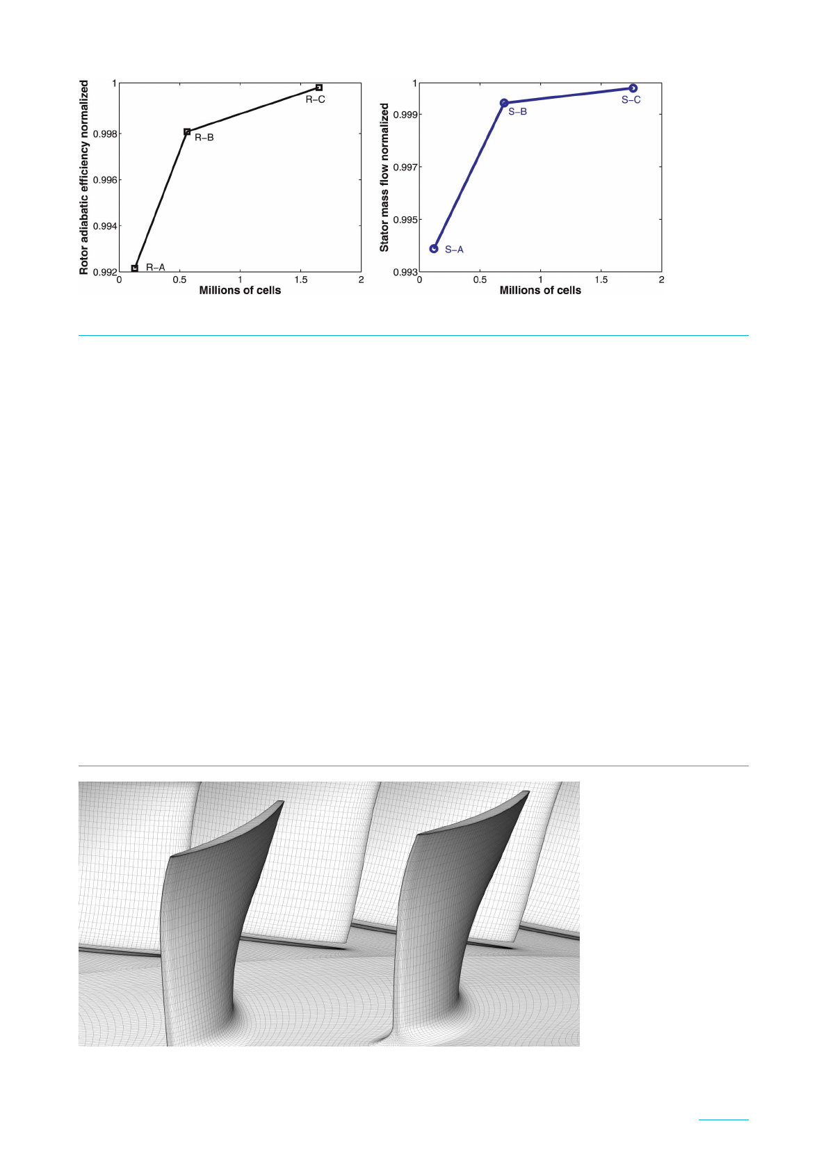
Several meshes were generated in order to perform a proper grid independence study, done separately for rotor
and stator. The grids were refined as uniformly as practical, however always keeping the boundary layer on the
walls resolved. Figure 2 displays three chosen meshes for rotor (labeled from coarsest to finest as R-A, R-B and
R-C) and stator (labeled as S-A, S-B and S-C), with isentropic efficiency and mass flow values normalized by the
finest grid, as a function of cell count. The deviation between the finest- and coarsest-grid values is less than 1%
for both domains, in the sense that all displayed grids capture the global flow behavior accurately enough. The
Grid Independence Index (Celik, 2008), formally derived based on the Richardson extrapolation (Roache,
1994), has been calculated and showed no oscillatory behavior. For the isentropic efficiency, the index between
finest and medium meshes is GCI
BC
= 0.24%, with apparent order of 1.94. The grids utilized for the current
stage are assembled together and shown in Figure 3. The number of nodes for the stage (if using one passage for
rotor and one for stator) is approximately 1.3 million.
As inlet boundary conditions, total pressure and temperature along with flow direction are implemented,
while on the outlet the static pressure is prescribed. Both on inlet and outlet, radial profiles experimentally
validated by the manufacturer are utilized. For the steady runs only, mixing-plane interface, with constant total
pressure (that is, no loss in through the interface), is used to account for the non-unitary pitch ratio.
(ii) Unsteady: two types of time-resolved simulations are performed, with and without the PGC disturbances.
The time discretization scheme utilized is the second order backward Euler, with a bounded high-resolution
Figure 1. The E3E high pressure compressor rotor.
J. Glob. Power Propuls. Soc. | 2018 | 2: 477–492 | https://doi.org/10.22261/JGPPS.F72OUU 479
Bicalho Civinelli de Almeida and Peitsch | Aeroelastic assessment of a HPC exposed to PGC disturb https://journal.gpps.global/a/F72OUU
discretization for advection and viscous terms. The solution is deemed periodically converged when the rela-
tive difference between two consecutive periods for some globally integrated parameter (such as compression
ratio or efficiency) or pressure probe falls below 0.05%. The attainment of quasi-convergence depends not
only on the blade passing frequency (BPF), but also on the combustion-originated frequency and intensity,
which in turn determines the required total run time.
The time resolution must be properly chosen to model the necessary phenomena without excessively consum-
ing computational resources. For the present case, the main (a priori known) frequencies to be modeled by the
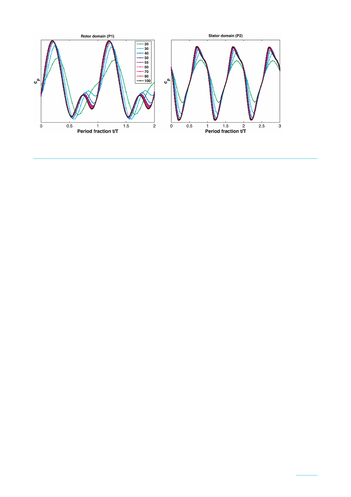
time march are the rotor BPF and the disturbance frequency. A temporal resolution study was performed to
determine the minimum time discretization required, using the number of time steps per rotor passing period
(TSRPP) as a parameter. Pressure time traces of two points located between rotor and stator (one in each
domain, respectively P1 and P2) are shown in Figure 4 (after periodic convergence is achieved). For both
domains, 50 TSRPP are enough to accurately capture the unsteady behavior. To enhance resolution for the dis-
turbed runs, a slightly higher value of 55 TSRPP has been chosen.
It is important to highlight that, under unsteady disturbances (additional to the rotor-stator frequency), the
required time step could become smaller. To assess whether 55 TSRPP is enough for the outlet disturbance with
the highest frequency here simulated (3.0 times the BPF), an extra run with halved time step (i.e., 110 TSRPP)
was carried out, for an extra full rotor revolution. In comparison with the 55 TSRPP setup, a relative difference
of 0.09% and 0.005% for isentropic efficiency and compression ratio, respectively, was found. Unsteady
damping, as well as modal forcing (both defined further), showed similar minimal changes. From that, the
current time resolution was deemed enough within the simulated disturbance range. Higher frequency distur-
bances could possibly require further time step refinement.
Figure 2. Grid independence study for fluid system, normalized by finest grid values.
Figure 3. Grids R-B and S-B for the simulated stage (rotor on the front and stator on the back), obtained after grid
independence study. Geometry is rescaled.
J. Glob. Power Propuls. Soc. | 2018 | 2: 477–492 | https://doi.org/10.22261/JGPPS.F72OUU 480
Bicalho Civinelli de Almeida and Peitsch | Aeroelastic assessment of a HPC exposed to PGC disturb https://journal.gpps.global/a/F72OUU
For the transient calculations, the number of rotor blades was reduced by one unit, so that 3 rotor passages
and 4 stator passages yield a unitary pitch ratio. This modification prevents phase errors which would incur
when using for example the profile-scaling method (Galpin et al., 1995). Time-inclining or -shifted methods,
such as (Giles, 1988)or(Gerolymos et al., 2002), are not physically consistent when disturbance frequencies dif-
ferent from the BPF are present in the system. In summary, the current unsteady simulation setup does not
induce frequency or phase errors due to non-unitary pitch ratio, with sliding meshes accurately modeling the
transient phenomena that takes place between rotor and stator. All unsteady disturbances are modeled by the
time marching scheme without further simplifications. The total number of nodes for this setup is approximately
4.6 million.
To model the PGC disturbances, time periodic boundary conditions at the stage outlet have been implemen-
ted. To the knowledge of the authors, no effective test rig or prototype coupling industrial axial compressor and
turbine to a pressure gain combustor has been built, in a fully coupled fashion. Ongoing investigations focus on
how to connect these components through adequate plena geometries, to minimize unsteadiness and therefore
prevent extra losses. Accordingly, due to the lack of more precise plenum information, it is assumed that the
unsteadiness reaching the compressor/combustor interface does not vary circumferentially, being here described
by harmonic fluctuations, as in Equation (1).
p(x,t)¼p(x)[1 þAdsin(2πfdt)] (1)
Here, Adand fdstand respectively for amplitude and frequency of the imposed harmonic disturbance on the
static pressure distribution p(x). Indeed, since the pressure is in this work prescribed radially, p(x)¼p(r) for
radius r. This approach assumes that the number of blades and vanes is rather larger than the number of com-
bustion units downstream, so that no disturbance wave interaction among combustor units is modeled.
(iii) Time-spectral: the frequency-domain method employed here is the nonlinear harmonic balance (Hall
et al., 2002) (also known as time spectral method (Gopinath and Jameson, 2005)). The time and
spatial dependent state variables are written as a Fourier series for a predetermined fundamental fre-
quency, whose first harmonics are iteratively and simultaneously solved with a pseudo time march.
Along this work, 3 harmonics (producing 7 time levels) have been used, after parametric studies
showed that more harmonics did not change the solution substantially. Additionally, 20 pseudo time
steps per oscillation period were enough to achieve the desired computational accuracy at rapid conver-
gence. The nonlinear harmonic balance is here utilized to determine the aerodynamic work Waero,as
definedinEquation(2).
Waero ¼ðtþT
tð‘
pv^
nd‘dt (2)
Here, pis the static pressure, vthe wall velocity vector and ^
nthe wall outwards pointing normal versor. The
surface integral takes place along the blade walls ‘. The aerodynamic work is integrated in time tduring one
Figure 4. Pressure probe periodically converged time trace, on rotor (P1) and stator (P2) domains. Several values for
time steps per rotor passing period (TSRPP) are shown.
J. Glob. Power Propuls. Soc. | 2018 | 2: 477–492 | https://doi.org/10.22261/JGPPS.F72OUU 481
Bicalho Civinelli de Almeida and Peitsch | Aeroelastic assessment of a HPC exposed to PGC disturb https://journal.gpps.global/a/F72OUU
Loading more pages...