
Two-step synthesis of Fe
2
O
3
and Co
3
O
4
nanoparticles: towards a general
method for synthesizing nanocrystalline metal oxides with high surface
area and thermal stability{
Junjiang Zhu,*
ab
Xiaoying Ouyang,
c
Ming-Yung Lee,
b
Ryan C. Davis,
c
Susannah L. Scott,*
bc
Anna Fischer
a
and Arne Thomas
a
Received 2nd August 2011, Accepted 11th October 2011
DOI: 10.1039/c1ra00552a
A simple, two-step method using activated carbon (AC) as a
support/scaffold was developed to synthesize metal oxide
nanocrystalline materials (NCMs). In the first step, metal nitrate
precursors were deposited by wet impregnation onto the AC,
then heated in argon at 350 uC to immobilize the metal oxides. In
the second step, the AC was removed by calcination in air at
500 uC, to obtain the unsupported metal oxide NCMs.
Characterization by N
2
-sorption isotherms, TGA, XPS and
EXAFS reveals that the metal oxide particles are crystalline and
nanometre-sized, with surface areas up to 148 m
2
g
21
. Moreover,
the TEM images show particle sizes in the range 5–10 nm, even
after calcination at 500 uC for 2 h. Their thermal stability and high
surface areas, together with the nanometre-sized structures, make
them promising materials for catalytic applications (e.g.,CO
oxidation).
Introduction
Nanocrystalline materials (NCMs) have attracted much attention in
recent years because of a wide variety of potential applications,
including catalysis, optics and chemical sensors.
1–8
In catalysis, it is
generally believed that, in addition to enhanced surface areas, NCMs
often display interesting and unexpected properties that are
qualitatively different from those of the corresponding bulk
materials, or of the atomic or molecular species from which they
are derived.
9
One well-known example is the use of gold for low
temperature CO oxidation: bulk gold shows no activity, while gold
nanoparticles (NPs) show high reactivity even at 77 K.
10–12
Defining and understanding the origin of the novel properties of
NCMs has stimulated much research, and consequently, methods to
prepare them have been extensively reported, both for metal
oxides
13–18
and for noble metals.
19–23
Compared to the preparation
of noble metal-based materials, the synthesis of metal oxide NCMs
can be more complex, because some metals are very reactive toward
oxygen, and agglomeration of oxide NPs occurs readily at moderate
temperatures. Straightforward, versatile routes for the synthesis of
thermally stable metal oxide NCMs are therefore of considerable
practical interest.
Activated carbon (AC) has long been recognized as a good
support for both noble and base metal catalysts, due to its
microporosity, multifunctional surface groups and high surface
area.
24–28
For a noble metal such as gold, Prati et al.
29,30
found that
when Au
3+
is first reduced to Au
0
in the presence of polyvinyl
alcohol (PVA) and then immobilized on AC, small gold particles
(y6 nm) can be obtained after removing the PVA at 350 uC. We
found that very small Co
3
O
4
?NPs (y5 nm) are obtained when a
metal nitrate-impregnated AC is heated in argon at 350 uC.
31,32
AC
has also been used to prepare unsupported metal oxides with high
surface areas and designed structures.
33–39
For example, Schu¨th
et al.
37
obtained metal oxides with surface areas ranging from 50 to
200 m
2
g
21
by calcining metal nitrates deposited on AC in air at 450–
800 uC. They reported better results for some metals (e.g., Cu) by
heating in the presence of a limited amount of air, and suggested that
slowing metal nitrate-catalyzed AC combustion reduces particle
sintering. These observations inspired us to prepare metal oxide NPs
using a prior immobilization step. By removing the AC scaffold in
air in a subsequent step, we hoped to obtain unsupported, metal
oxide NCMs with small particle sizes and high surface areas.
Results and discussion
For preparation of the metal oxide NCMs, a metal nitrate was first
deposited by wet impregnation onto a microporous AC. The
resulting material (denoted M/AC-1, where M is Co, Fe) was then
dried and heated in a stream of argon at 350 uC, to generate and
immobilize the metal oxide NPs on AC, denoted M/AC-2.
Subsequently, the solid was allowed to cool to room temperature
and heated again to 500 uC in air for 2 h, to remove the AC scaffold
and recover the unsupported, nanocrystalline metal oxide.
a
Department of Chemistry, Technical University of Berlin, Englische
Straße 20, 10587, Berlin, Germany. E-mail: ciaczjj@gmail.com (J. Zhu)
b
Department of Chemical Engineering, University of California, Santa
Barbara, 10 Mesa Road, Santa Barbara, CA, 93106-5080, USA.
c
Department of Chemistry & Biochemistry, University of California, Santa
Barbara, 10 Mesa Road, Santa Barbara, CA, 93106-9510, USA
{Electronic supplementary information (ESI) available: Experimental
details, additional N
2
-sorptionisotherms,XRD,XPS,TGA,andTEM
images of the metal oxides before and after their use as catalysts. See DOI:
10.1039/c1ra00552a
RSC Advances Dynamic Article Links
Cite this: RSC Advances, 2012, 2, 121–124
www.rsc.org/advances COMMUNICATION
This journal is ßThe Royal Society of Chemistry 2012 RSC Adv., 2012, 2, 121–124 |121
Published on 08 November 2011. Downloaded on 31/03/2016 08:41:06.
View Article Online
/ Journal Homepage
/ Table of Contents for this issue
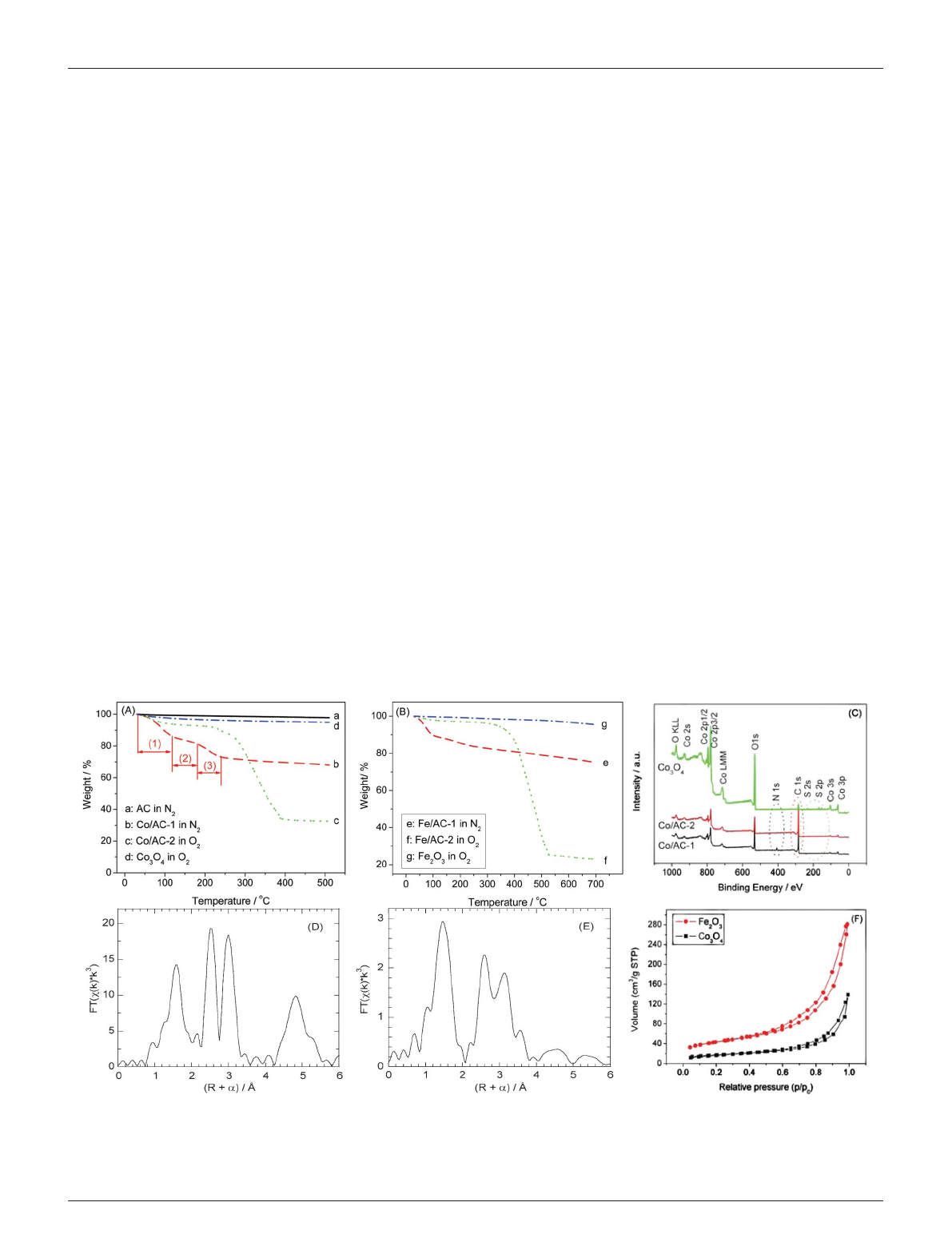
Fig. 1(A) and (B) show the thermal behavior of the materials at
each stage during their synthesis, as monitored by thermogravimetric
analysis (TGA). AC is thermally stable up to approx. 560 uCin
oxygen (see Fig. S1{), and as expected no appreciable weight loss was
observed for the AC at T,500 uC in the inert atmosphere (curve
‘‘a’’). Co/AC-1 (curve ‘‘b’’) shows a stepwise weight loss during
thermal treatment in the inert atmosphere. Stage (1), at T,120 uC,
is ascribed to loss of water and other adventitious adsorbates
acquired during sample storage; stage (2), at 120 ,T,180 uC, is
caused by transformation of [Co(OH
2
)
6
](NO
3
)
2
introduced in the
impregnation step to [Co
3
[NO
3
]
2
(OH)
4
]; stage (3), at 180 ,T,
240 uC, corresponds to the decomposition of [Co
3
[NO
3
]
2
(OH)
4
]toa
cobalt oxide (Co
3
O
4
).
31
These transformations are similar to those
observed previously in the synthesis of supported NiO nanoparti-
cles.
2
After formation of the supported metal oxide, the AC scaffold
was removed in O
2
, as represented by curve ‘‘c’’. It shows that (i) no
appreciable weight loss occurs at 120 ,T,240 uC, confirming that
most of the nitrate was removed during the first thermal treatment
step; and (ii) AC is fully removed at T,400 uC, suggesting that the
final product calcined at 500 uC should not contain any residual AC
scaffold. This is further evidenced by the TGA behavior of the
product (curve ‘‘d’’), which shows a weight loss of less than 5% at T
=510uCinO
2
. Similar changes were observed for M = Fe, except
that the temperature required for complete removal of the AC
scaffold (curve ‘‘f’’) was slightly higher than 500 uC. Nevertheless, the
minorweightlossobservedforFe
2
O
3
(,5%, curve ‘‘g’’) suggests that
AC had been completely removed from the final product.
Thus the characterization and reactivity results below are
considered to pertain exclusively to the unsupported metal oxides.
By comparing the weight losses of samples Co/AC-2 and Fe/AC-2
with that of the unmodified AC, we estimate the loadings of Co
3
O
4
and Fe
2
O
3
prior to calcination to be 22 and 14 wt%, respectively.
Results obtained by X-ray photoelectron spectroscopy (XPS)
confirm our conclusions based on TGA measurements. Fig. 1(C)
showsthattheN1ssignalisnolongerpresentafterthesamplehas
been heated in Ar at 350 uC for 2 h, indicating that the metal nitrate
decomposes completely to the metal oxide. Also, the intensity of the
C 1s signal is strongly attenuated in the final product compared to
the sample prior to calcination, indicating that AC is indeed removed
in the second step. (The weak residual C 1s signal observed for the
metal oxide arises due to the carbon tape used to hold the sample in
place.) The small amount of S is presumably due to impurities in the
AC scaffold: ca. 11 wt% non-combustible impurities are present
according to the TGA of AC recorded in air, and may include S, Al,
Si, etc.
In the powder X-ray diffraction (XRD) patterns of the metal
oxide NCMs, the reflections are very weak and broad (see Fig. S3{),
complicating their assignment and implying that the particle sizes are
very small. This agrees with observations made previously for AC-
supported cobalt oxide (Co
3
O
4
/AC), in which peak intensities were
very low due to the small particle size (ca. 5nm).
31
Thus, we infer
that the metal oxide NPs formed during the first preparation step do
not grow appreciably when the AC support is removed. Low peak
intensities could also indicate that the metal oxides are in an
amorphous state, however, this possibility can be excluded since well-
resolved lattice fringes are observed in the high resolution
transmission electron microscopy (HR-TEM) images (Fig. 2(C)),
typical of a crystalline structure. Consequently, phase assignment
was carried out using extended X-ray absorption fine structure
(EXAFS). The results shown in Fig. 1(D) and (E) are consistent with
spinel Co
3
O
440
and a-Fe
2
O
341
for the cobalt and iron oxides,
respectively. The ratio of peak heights for the M–O and M–M
scattering paths is a reflection of the particle size.
42
We estimate that
the Fe
2
O
3
particles are in the range 2–10 nm, by comparison to
Fig. 1 TGA curves for Co-containing (A) and Fe-containing samples (B), as well as XPS spectra for the Co-containing samples (C), before and after removal
of the AC scaffold; R-space EXAFS at the Co K-edge for unsupported Co
3
O
4
_NSMs (D), and at the Fe K-edge for unsupported Fe
2
O
3
_NSMs (E), and N
2
-
sorption isotherms for Co
3
O
4
_NSMs and Fe
2
O
3
_NSMs (F). ‘‘M/AC-1’’ and ‘‘M/AC-2’’ represent materials before and after treatment in the inert atmosphere,
respectively.
122 |RSC Adv., 2012, 2, 121–124 This journal is ßThe Royal Society of Chemistry 2012
Published on 08 November 2011. Downloaded on 31/03/2016 08:41:06.
View Article Online
spectra reported by Kitagami et al.
43
These observations confirm our
idea that the two-step synthesis method leads to nanometre-sized,
crystalline metal oxide particles.
N
2
-sorption isotherms were also recorded, in order to assess the
porosity of the unsupported metal oxides (see Fig. 1(F)). Both show
type II isotherms with a hysteresis loop, indicating a porous structure
(presumably due to interparticle porosity). The surface areas
calculated by the Brunauer–Emmett–Teller method are 60 and
148 m
2
g
21
for Co
3
O
4
and Fe
2
O
3
?NCMs, respectively. These high
surface areas are consistent with the porous structures, as shown by
Fig. 2(B)).
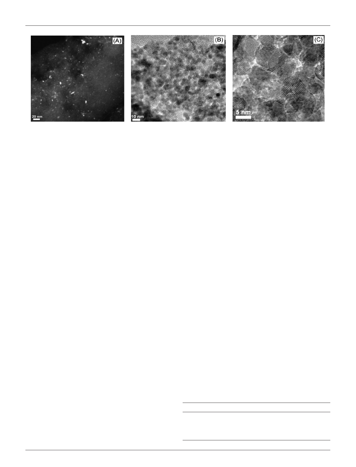
The morphology and average particle size of the metal oxide
NCMs are directly accessible from the TEM images shown in Fig. 2.
For the AC-supported metal oxides obtained in the first step, the
particles are very small and difficult to see in bright-field mode,
therefore the dark-field mode was also used. Fig. 2(A) shows that the
metal oxide particles are highly dispersed, and that the particle size is
generally ¡5 nm. A few large particles (,15 nm) are also present.
They are attributed to concentration of the deposited metal ions on
the support surface during the drying process, which is an
unavoidable consequence of the impregnation method. After
removal of the AC scaffold, agglomerated metal oxide nanoparticles
are observed, however the small particle sizes from 5 to 10 nm show
that they have not sintered to a larger extent. This is also seen by the
porous morphology evident in Fig. 2B even after calcination at
500 uC for 2 h. This suggests that metal oxide NCMs prepared by
this route have high thermal stability. The porous structure and small
particle size are in agreement with those inferred by N
2
-sorption
isotherms and EXAFS (Fig. 1).
These results indicate that AC-supported metal oxide NCMs
formedbyheatinginaninertatmosphere during the first synthesis
step retain their structure when the AC support is removed in the
second step. In order to demonstrate the advantage of prior metal
oxide formation and immobilization by the two-step method,
Fe
2
O
3
?NPs were also prepared using the one-step method (direct
calcination of the supported metal nitrate) according to Schu¨th
et al.
37
The product is denoted as ‘‘Fe
2
O
3
_NCM_I’’, and its
properties are compared with those of Fe
2
O
3
_NCM_II (prepared
using the two-step method) in Table 1. Clearly, the latter has a higher
surface area and pore volume, as well as a smaller particle size,
indicating that immobilization in an inert atmosphere is indeed
beneficial for the preparation of unsupported metal oxide NPs with
high surface area and porosity. Presumably decomposition of the
nitrate ions in the absence of air limits the exotherm in the
subsequent calcination step, as proposed by Schu¨th et al.
37
The
resulting metal oxide NPs dispersed on AC are stable enough to
resist agglomeration.
The high calcination temperature (500 uC) suggests that the
NCMs may be robust enough for catalytic applications that require
elevated temperatures, which represent a challenge for NCMs.
Furthermore, the higher surface areas of metal oxides obtained using
the two-step synthesis method described here should be beneficial for
their catalytic activity. The catalytic performance of Fe
2
O
3
_NCM_II
was studied in CO oxidation, a reactionthatisoftenrequiredto
operate at elevated temperatures.
44,45
For comparison, the catalytic
performance of ‘‘Fe
2
O
3
_NCM_I’’ and an additional Fe
2
O
3
sample
prepared by an organic solution method without the AC scaffold
(denoted as Fe
2
O
3
_Org, see SI{) were also studied. The results are
shown in Fig. 3.
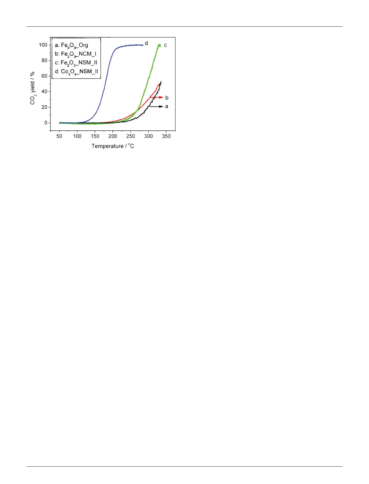
Although the temperatures for onset of reactivity are similar for all
three iron oxide catalysts (ca. 200 uC), the conversion increases most
rapidly with temperature for Fe
2
O
3
_NCM_II, and at 330 uC, the
CO
2
yield (100%) is far higher than for ‘‘Fe
2
O
3
_NCM_I’’ or
Fe
2
O
3
_Org (both ca. 50%). Comparison of the TEM images for
Fe
2
O
3
_NCM_II before and after its use in CO oxidation shows no
appreciable change in the particle size (Fig. S6{), confirming its
stability as a high-temperature catalyst. Even more interesting, the
Co
3
O
4
?NCMs show much better catalytic activity than
Fe
2
O
3
?NCMs, to be discussed in our forthcoming work.
Conclusions
In summary, we have synthesized crystalline, nanometre-sized iron
and cobalt oxides by a two-step method using activated carbon (AC)
as a support/scaffold, resulting in particle sizes ranging from 5 to
10nmandsurfaceareasupto148m
2
g
21
.ThemetaloxideNCMs
Fig. 2 HR-TEM images for AC-supported Co
3
O
4
?NCMs, obtained in the first step (A), dark-field; and unsupported Co
3
O
4
?NCMs obtained in the second
step (B), (C), bright-field. Note: for results involving Fe
2
O
3
,seetheESI.{
Table 1 Comparison of the textural properties of Fe
2
O
3
?NPs, prepared
by one- and two-step methods
Catalyst S.A./m
2
g
21a
P.V./cm
3
g
21b
P.S./nm
c
Fe
2
O
3
_NCM_II 148 0.43 5–10
Fe
2
O
3
_NCM_I 59 0.28 y20
a
Surface area determined by BET method (5-points).
b
Pore volume
calculated at p/p
0
= 0.99.
c
Particle size evaluated from TEM images.
This journal is ßThe Royal Society of Chemistry 2012 RSC Adv., 2012, 2, 121–124 |123
Published on 08 November 2011. Downloaded on 31/03/2016 08:41:06.
View Article Online
persist at temperatures up to 500 uC without significant agglomera-
tion, thus ensuring their stability under most reaction conditions.
Furthermore, because the synthesis method described here is very
simple,weexpectittobeageneralmethodforthepreparationof
metal oxide NCMs. The only requirement is that the metal precursor
be soluble, so that it can be deposited on the AC support by wet
impregnation.
Acknowledgements
Financial support from the German Research Foundation
(DFG, grant No. TH 1463/5-1), the Cluster of Excellence
‘‘Unifying Concepts in Catalysis’’ (EXL 31411), and the US
Department of Energy (DE-FG02-03ER15467) are gratefully
acknowledged. Portions of this work were performed at the
Stanford Synchrotron Radiation Lightsource, a national user
facility operated by Stanford University on behalf of the U.S.
Department of Energy, Office of Basic Energy Sciences.
References
1 M. M. Titirici, M. Antonietti and A. Thomas, Chem. Mater., 2006, 18,
3808.
2 J.R.A.Sietsma,J.D.Meeldijk,J.P. den Breejen, M. Versluijs-Helder,
A. J. van Dillen, P. E. de Jongh and K. P. de Jong, Angew. Chem., Int. Ed.,
2007, 46, 4547.
3 P.Poizot,S.Laruelle,S.Grugeon, L. Dupont and J. M. Tarascon, Nature,
2000, 407,496.
4 L.J.Zhi,Y.S.Hu,B.ElHamaoui,X.Wang,I.Lieberwirth,U.Kolb,
J. Maier and K. Mullen, Adv. Mater., 2008, 20, 1727.
5 A. T. Bell, Science, 2003, 299, 1688.
6 R. Schlogl and S. B. Abd Hamid, Angew. Chem., Int. Ed., 2004, 43, 1628.
7 W.Y.Li,L.N.XuandJ.Chen,Adv. Funct. Mater., 2005, 15, 851.
8 H.CaoandS.L.Suib,J. Am. Chem. Soc., 1994, 116, 5334.
9S.O’Brien,L.BrusandC.B.Murray,J. Am. Chem. Soc., 2001, 123,
12085.
10 M. Haruta, Catal. Today, 1997, 36,153.
11 M. Haruta, CATTECH, 2002, 6,102.
12 G. J. Hutchings and M. Haruta, Appl. Catal., A,2005,291,2.
13 A.Murali,A.Barve,V.J.Leppert,S.H.Risbud,I.M.Kennedyand
H. W. H. Lee, Nano Lett.,2001,1, 287.
14 Y. D. Wang, C. L. Ma, X. D. Sun and H. D. Li, Inorg. Chem. Commun.,
2002, 5,751.
15 X.L.Xu,J.D.GuoandY.Z.Wang,Mater. Sci. Eng., B, 2000, 77, 207.
16 S. Castro-Garcia, S. Yanez-Vilar, M. Sanchez-Andujar, C. Gomez-
Aguirre, J. Mira and M. A. Senaris-Rodriguez, J. Solid State Chem.,
2009, 182, 2685.
17 X. H. Liu, A. Yan, G. Qiu, N. Zhang, R. R. Shi, R. Yi, M. Tang and
R. C. Che, Solid State Commun., 2007, 144, 315.
18 V. Polshettiwar, B. Baruwati and R. S. Varma, ACS Nano, 2009, 3,728.
19 B.H.Wu,Y.J.Kuang,X.H.ZhangandJ.H.Chen,Nano Today, 2011,
6, 75.
20 J.H.He,T.KunitakeandA.Nakao,Chem. Mater., 2003, 15, 4401.
21 Y. W. Tan, X. H. Dai, Y. F. Li and D. B. Zhu, J. Mater. Chem., 2003, 13,
1069.
22 C. L. Lee, C. C. Wan and Y. Y. Wang, Adv. Funct. Mater.,2001,11, 344.
23 J. J. Zhu, X. Xie, S. A. C. Carabineiro, P. B. Tavares, J. L. Figueiredo,
R. Schomaecker and A. Thomas, Energy Environ. Sci., 2011, 4, 2020.
24 F. Rodriguez-Reinoso, Carbon,1998,36,159.
25M.D.Hughes,Y.J.Xu,P.Jenkins,P.McMorn,P.Landon,D.I.
Enache,A.F.Carley,G.A.Attard,G.J.Hutchings,F.King,E.H.Stitt,
P.Johnston,K.GriffinandC.J.Kiely,Nature, 2005, 437, 1132.
26 D.S.Su,J.Zhang,B.Frank,A.Thomas,X.C.Wang,J.Paraknowitsch
and R. Schlogl, ChemSusChem, 2010, 3,169.
27 J. L. Figueiredo and M. F. R. Pereira, Catal. Today, 2010, 150,2.
28 M.L.Toebes,F.F.Prinsloo,J.H.Bitter,A.J.vanDillenandK.P.de
Jong, J. Catal., 2003, 214, 78.
29 L. Prati and G. Martra, Gold Bull.,1999,32,96.
30 L. Prati and M. Rossi, J. Catal., 1998, 176,552.
31 J. J. Zhu, K. Kailasam, A. Fischer and A. Thomas, ACS Catal., 2011, 1,
342.
32 J. J. Zhu, J. L. Faria, J. L. Figueiredo and A. Thomas, Chem.–Eur. J.,
2011, 17, 7112.
33 H.J.Fan,Q.Xu,Y.Q.Guo,Q.PengandZ.Z.Hou,Mater. Sci. Eng., A,
2006, 422, 272.
34 H.J.Fan,Q.Xu,J.G.LiandY.X.Cao,J. Am. Ceram. Soc., 2006, 89,
3065.
35 W. Rarog-Pilecka, E. Miskiewicz and Z. Kowalczyk, Catal. Commun.,
2008, 9,870.
36 H.N.Yang,L.F.Liu,F.L.YangandJ.C.Yu,J. Zhejiang Univ., Sci., A,
2008, 9,981.
37 M. Schwickardi, T. Johann, W. Schmidt and F. Schu¨th, Chem. Mater.,
2002, 14, 3913.
38 S.A.C.Carabineiro,S.S.T.Bastos,J.J.M.Orfao,M.F.R.Pereira,J.L.
Delgado and J. L. Figueiredo, Appl. Catal., A, 2010, 381, 150.
39 S.A.C.Carabineiro,S.S.T.Bastos,J.J.M.Orfao,M.F.R.Pereira,J.J.
Delgado and J. L. Figueiredo, Catal. Lett., 2010, 134, 217.
40 B. Ernst, A. Bensaddik, L. Hilaire, P. Chaumette and A. Kiennemann,
Catal. Today, 1998, 39, 329.
41 F. Jiao, A. Harrison, J. C. Jumas, A. V. Chadwick, W. Kockelmann and
P. G. Bruce, J. Am. Chem. Soc.,2006,128,5468.
42 T. Liu, L. Guo, Y. Tao, T. D. Hu, Y. N. Xie and J. Zhang, Nanostruct.
Mater., 1999, 11, 1329.
43 M.Kitagami,T.Konishi,T.Kaneko,M.Sakamaki,L.Lin,J.G.Lin,
D. Arvanitis and T. Fujikawa, Photon Factory Activity Report 2006 #24
Part B, 2007, 12C/2006G356.
44 Y. H. Zheng, Y. Cheng, Y. S. Wang, F. Bao, L. H. Zhou, X. F. Wei, Y. Y.
Zhang and Q. Zheng, J. Phys. Chem. B,2006,110, 3093.
45 P. Li, D. E. Miser, S. Rabiei, R. T. Yadav and M. R. Hajaligol, Appl.
Catal., B, 2003, 43,151.
Fig. 3 Temperature-programmed reaction profiles for CO oxidation over
three unsupported Fe
2
O
3
catalysts, as well as over Co
3
O
4
?NCMs.
Conditions: 0.4 vol% CO + 10 vol% O
2
in Ar; 50 mg catalyst; total flow
rate 50 mL min
21
. Temperature ramp 5 uCmin
21
.
124 |RSC Adv., 2012, 2, 121–124 This journal is ßThe Royal Society of Chemistry 2012
Published on 08 November 2011. Downloaded on 31/03/2016 08:41:06.
View Article Online
Loading more pages...