
fluids
Article
Design of a Fluidic Actuator with Independent Frequency and
Amplitude Modulation for Control of Swirl Flame Dynamics
Amrit Adhikari 1,2, Thorge Schweitzer 1,2, Finn Lückoff 1,* and Kilian Oberleithner 1,*
Citation: Adhikari, A.; Schweitzer, T.;
Lückoff, F.; Oberleithner, K. Design of
a Fluidic Actuator with Independent
Frequency and Amplitude
Modulation for Control of Swirl
Flame Dynamics. Fluids 2021,6, 128.
https://doi.org/10.3390/fluids6030128
Academic Editor: V’yacheslav
Akkerman
Received: 26 February 2021
Accepted: 17 March 2021
Published: 20 March 2021
Publisher’s Note: MDPI stays neutral
with regard to jurisdictional claims in
published maps and institutional affil-
iations.
Copyright: © 2021 by the authors.
Licensee MDPI, Basel, Switzerland.
This article is an open access article
distributed under the terms and
conditions of the Creative Commons
Attribution (CC BY) license (https://
creativecommons.org/licenses/by/
4.0/).
1Laboratory for Flow Instabilities and Dynamics, Technische Universität Berlin, Müller-Breslau-Straße 8,
2FDX Fluid Dynamix GmbH, Rohrdamm 88, 13629 Berlin, Germany
*Correspondence: finn.lueckof[email protected] (F.L.); [email protected] (K.O.);
Tel.: +49-30-314-73874 (F.L.)
Abstract:
Fluidic actuators are designed to control the oscillatory helical mode, called a precessing
vortex core (PVC), which is often observed in gas turbine combustors. The PVC induces large-
scale hydrodynamic coherent structures, which can considerably affect flow and flame dynamics.
Therefore, appropriate control of this structure can lead to a more stable and efficient combustion
process. Currently available flow control systems are designed to control the PVC in laboratory-scale
setups. To further develop these systems and find an approach applicable to the industrial scale, a
new actuator design based on fluidic oscillators is presented and studied in this paper. This actuator
allows for independently adjusting forcing frequency and amplitude, which is necessary to effectively
target the dynamics of the PVC. The functionality and flow control of this actuator design are studied
based on numerical simulations and experimental measurements. To verify the flow control authority,
the actuator is built into a prototype combustor test rig, which allows for investigating the impact
of the actuator’s forcing on the PVC at isothermal conditions. The studies conducted in this work
prove the desired functionality and flow control authority of the 3D-printed actuator. Accordingly, a
two-part stainless steel design is derived for future test conditions with flame.
Keywords: active flow control; fluidic oscillator; precessing vortex core; swirl flame dynamics
1. Introduction
Turbulent flows can be found in many technical applications. For example, the
operation of turbomachines relies primarily on the working fluid, which flows through the
machine in a turbulent manner. The inherent dynamics and instabilities of these flows can
severely impact the machine’s operation. These instabilities can lead to the formation of
large-scale coherent flow structures that produce oscillatory dynamics with high amplitude.
These oscillations compromise the overall flow field and, therefore, the operation of the
machine. To minimize this impact and to guarantee the safe and reliable operation of the
machine, efficient flow control methods are required.
In modern gas turbines, a turbulent swirling flow is generated inside the combustor
to allow for aerodynamic stabilization of the flame [
1
,
2
]. This is achieved by exploiting a
phenomenon known as vortex breakdown, which results in a central recirculation zone in
the vicinity of the nozzle outlet [
3
–
5
]. The swirling jet emanating from the burner nozzle
into the combustion chamber generates shear layers between the central recirculation zone
and the jet (inner shear layer) and between the jet and the surrounding fluid (outer shear
layer). These shear layers provide a gradient of flow velocities, which allows matching
with the flame’s burning velocity, leading to aerodynamic stabilization. However, these
shear layers are prone to hydrodynamic instabilities, leading to large-scale coherent flow
oscillations. Due to the vortex breakdown phenomenon, the flow inside the gas turbine
combustor is globally unstable and produces a helical-shaped large-scale coherent flow
structure, known as the precessing vortex core (PVC). The PVC generates alternating
Fluids 2021,6, 128. https://doi.org/10.3390/fluids6030128 https://www.mdpi.com/journal/fluids

Fluids 2021,6, 128 2 of 16
vortices meandering along the inner shear layer in the downstream direction that are
characterized by a certain oscillation frequency [
6
,
7
]. Under reacting conditions involving
a swirl-stabilized flame, a PVC arises depending on the flame shape and the associated
density field in the region of the upstream end of the central recirculation zone. Whereas
flames that are attached to the nozzle outlet typically suppress the PVC, detached flames
that are stabilized further downstream let a PVC arise in the shear layers around the burner
outlet [
8
,
9
]. If a PVC is present in the reacting flow configuration, the flame dynamics,
mixing of fuel and air, and flame stability can be considerably influenced by the PVC-
induced vortices [
10
–
16
]. These vortices can affect the generation of pollutant emissions
and the flame response to (thermo-)acoustic perturbations [
16
–
19
]. Therefore, the control of
the PVC allows for controlling thermoacoustic oscillations and pollutant emissions, which
are both key design parameters of premixed combustion systems.
To control the PVC in combustion systems, Lückoff et al. developed an active flow
control system [
20
–
23
]. that relies on a loudspeaker-based actuator, which works according
to the zero-net-mass-flux principle [
24
]. It combines the advantages of actuator designs that
were successfully developed for isothermal flows [
7
,
25
]. This active flow control system
may not only be used to suppress the instabilities driving the PVC, but also to excite it.
This allows the investigation of its exclusive impact on other flow and flame quantities, as
illustrated by an example in Figure 1.
Figure 1.
Precessing vortex core (PVC) mode and flame dynamics reconstructed from time-resolved particle image
velocimetry (PIV) and OH*-chemiluminescence snapshots revealing PVC-induced vortices (gray-scale) overlaid with heat
release rate indicating the corresponding variation in the flame. Top row: phase-averaged heat release rate fluctuations in
longitudinal section; bottom row: PVC-induced heat release rate fluctuations in cross-sectional view (x/D = 0.75). Heat
release rate is normalized to maximal values.
The shown phase-averaged flow and flame dynamics were measured in a gas turbine
combustor with active PVC flow control. They reveal the alternating (helical-shaped)
vortices induced by the excited PVC as they propagate along the inner shear layer before
they collide with the combustion chamber wall. In the cross-sectional view (bottom row in
Figure 1), the helical movement in the clockwise direction induced by the PVC is depicted.
The flame surface dynamics, indicated by the phase-averaged OH*-chemiluminescence
fluctuations, are clearly driven by the vortex dynamics, as they entrain a very inflammable
composition of fuel–air mixture and high-temperature burnt gas from the central recircu-
lation zone. The acquisition and post-processing of the required data needed to derive

Fluids 2021,6, 128 3 of 16
this illustration are documented in some of our previous publications [
26
,
27
]. Applying
different actuation amplitudes generates PVCs of different strengths which allows for
investigating the impact of the PVC on important design parameters of the premixed
combustion system such as thermoacoustic instabilities and pollutant emissions. Lückoff
et al. [
23
,
28
] showed that an excited PVC can damp the growth rate and amplitude of
thermoacoustic modes, which lead to a more stable combustion process. The loudspeaker-
based flow control system was applied to show that an excited PVC slightly increases the
NOx
emission level in partially and perfectly premixed flames due to increased vorticity [
27
].
The loudspeaker-based flow control design by Lückoff et al. is well-suited to academic
purposes on a laboratory scale to study PVCs. However, robustness and applicability
are lacking to implement this design as used in an industrial-scale machine. Therefore,
an alternative actuator concept needs to be derived that is more robust and preferably
maintenance-free. The obvious choice is fluidic oscillators, which are capable of generating
an oscillating synthetic jet without moving parts [26,29].
Fluidic devices were first developed in the early 1960s at Harry Diamond Labo-
ratories as logic elements for missile control systems [
30
]. These elements included
oscillators [
31
,
32
], amplifiers [
33
], and classic logic gates [
34
]. With the increase in the
use of electronic control systems and their increased reliability, fluidic control systems
were quickly replaced. In recent years, fluidic oscillators have seen a rise in interest for
addressing modern engineering problems. They are used in active flow control [
35
–
37
],
windshield wipers [
38
], future combustion processes [
39
,
40
], and the generation of mi-
crobubbles in bioreactors [
41
,
42
]. However, fluidic bistable amplifiers, sometimes called
fluidic switches, have not been used as much as oscillators. Bobusch and Tesaˇr [
43
,
44
]
demonstrated their use as high-speed gas valves in harsh environments. They can also
be used to create high-frequency fluidic oscillators [
45
]. In comparison with traditional
actuators, fluidic devices are virtually maintenance-free because they contain no moving
parts. Additionally, they are not affected by radiation, shock, or temperature changes, and
can be run from a pressure reservoir without any electronic parts. Further information
on the functioning and application of fluidic oscillators may be found in the works of
Gregory [46], Tesaˇr [47,48], Foster [49], Raghu [35], and Bobusch [43].
Common feedback-type fluidic oscillators have a linear relationship between mass
flow and frequency [
40
]. In this case, the mass flow governs the actuator’s forcing am-
plitude. Therefore, the independent control of actuation frequency and amplitude is
impossible, but is necessary for successful control of the PVC dynamics, as achieved
with the loudspeaker-based actuator [
20
]. Tesaˇr [
50
] offered a possibility, of replacing the
loudspeaker-based actuator with a more robust actuation system to facilitate the control of
the PVC in industrial-scale gas turbine combustors. Following the approach of Tesaˇr [
50
],
the combination of a fluidic oscillator and a fluidic amplifier, which allows for the de-
coupling of the actuation amplitude (proportional to the mass flow) and frequency, was
investigated in this study.
In the following section, the design of the newly developed fluidic actuator is described
and its functionality is illustrated using numerical simulations. Subsequently, a short
description of the flow control approach is provided, which includes an introduction
to the concept of lock-in serving as a proof-of-concept of the actuation principle. The
fourth section deals with the experimental validation and proof-of-concept of the new
fluidic actuator in two different experimental setups. Finally, conclusions are drawn and
an outlook for future studies are provided. This involves the presentation of a two-part
stainless steel design of the successfully tested actuator for experiments under reacting
flow conditions with flame.
2. Design and Functionality of the OsciAmp Fluidic Oscillator
The new actuator, named OsciAmp, was designed based on the master–slave concept.
It is a two-stage layout that generates a desirable frequency in an oscillator stage, whose
output switches a large mass flow downstream of an amplifier stage. In this context,
Fluids 2021,6, 128 4 of 16
the oscillator acts as a master providing frequency commands and the amplifier, as the
slave, obeys and switches accordingly. Although the working principle seems simple, the
practical implementation of this concept is demanding; hence, its industrial implementation
has not yet been achieved, most probably because the matching of the properties between
the oscillator and amplifier is a tedious task. This difficulty arises basically from the large
number of inlets and outlets consisting of different conditions, i.e., pressure and flow rate,
which have to be matched simultaneously [50].
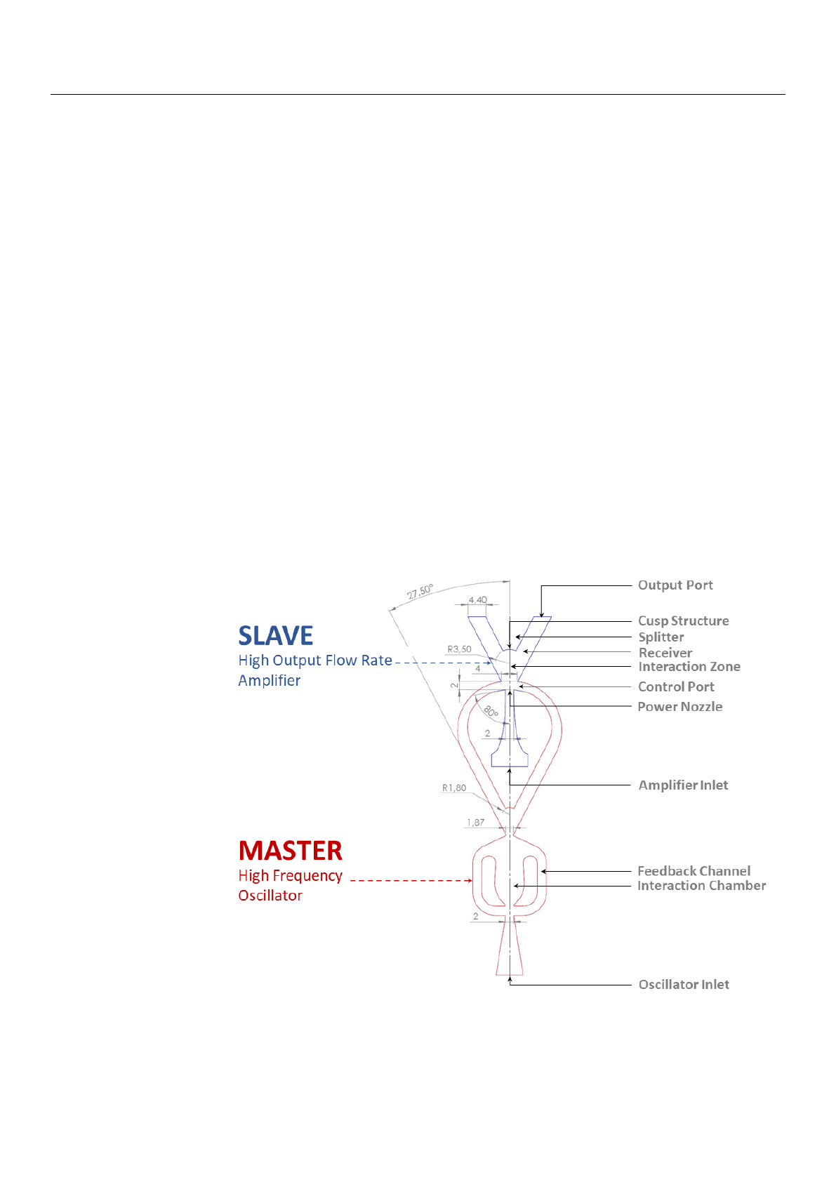
Figure 2shows the implementation of the master–slave concept used in this work.
The oscillator (illustrated in red) acts as a master and the amplifier (illustrated in blue)
obeys as a slave, which results in well-defined alternating synthetic jets at the two output
ports. The oscillator contains an inlet and two outlets. The outlets of the oscillator are the
(frequency) control ports in the amplifier. The amplifier has its own inlet and two outlets.
The amplifier inlet flow is subjected to the control flows of the oscillator, which switches
between the two actuator outlet ports. In this configuration, the magnitude of the mass flow
through the actuator, and with the forcing amplitude, is mainly governed by the amplifier
inlet flow. The forcing frequency is determined by the oscillator inlet flow. Accordingly,
independent control of forcing amplitude and frequency can be achieved. The OsciAmp
is a combination of the fluidic oscillator investigated in a previous study [
51
] with the
fluidic amplifier described above. Instead of using an amplifier with a Spyropoulos-type
feedback as the master (used by Tesaˇr [
50
]), a sweeping-jet-type oscillator with an attached
splitter geometry is used. This allows the master stage to be entirely two-dimensional and
simplifies manufacturing down the line. The same sweeping oscillator was used in the
aforementioned study [
51
], allowing the master to operate in the same frequency band
without requiring several tuning iterations to match the two systems.
Figure 2.
Design of the actuator based on the master–slave concept. The high-frequency oscillator, as
the master, provides frequency information to the high-flow output of the amplifier, which acts as a
slave.
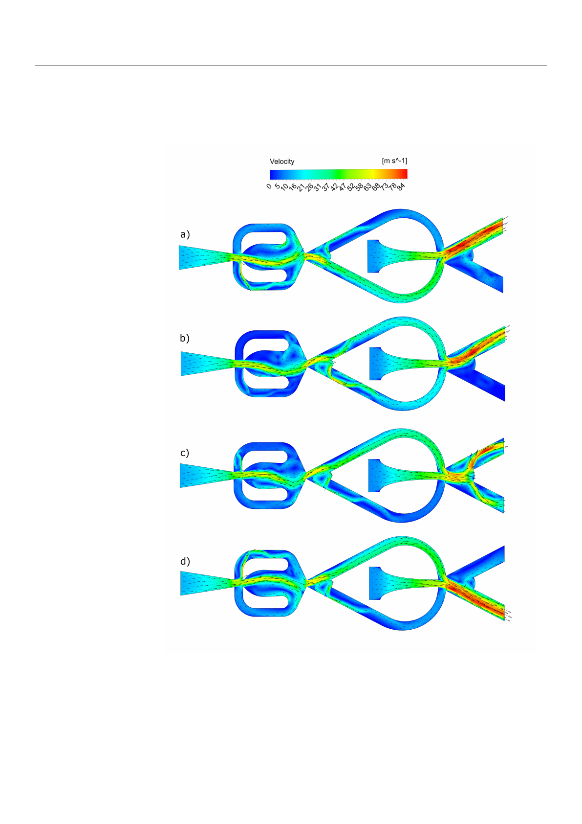
To test the functionality of the design and visualize the flow field inside the actuator,
2D-incompressible unsteady Reynolds-averaged Navier–Stokes (URANS) simulations
Fluids 2021,6, 128 5 of 16
were performed. The inlet flow rate for the oscillator and amplifier were set to 0.25 g/s and
a k-
ω
-SST model was selected for turbulence modeling. Figure 3shows different phase
angles of the combined system and the oscillator shows full control over the switching
action of the amplifier.
Figure 3.
Numerical results for a 2D unsteady Reynolds-averaged Navier–Stokes (URANS) simula-
tion of the actuator’s internal flow field (
a
–
d
) from top to bottom: (
a
) stable condition top output;
(
b
) the oscillator output is switching to the upper control channel, the amplifier flow is beginning
to detach from the top attachment wall; (
c
) the oscillator flow is fully switched to the upper control
channel and the amplifier flow is in the process of switching; (d) stable condition bottom output.
3. Flow Control Approach and Lock-In Investigation
In the present experimental setup, the developed fluidic oscillator was applied in an
open-loop control approach. Accordingly, no feedback-signal from some sort of sensor was
Loading more pages...