
Lab on a Chip
PAPER
Cite this: Lab Chip,2014,14,2115
Received 3rd February 2014,
Accepted 24th March 2014
DOI: 10.1039/c4lc00145a
www.rsc.org/loc
Feedback control of inertial microfluidics using
axial control forces†
Christopher Prohm*and Holger Stark
Inertial microfluidics is a promising tool for many lab-on-a-chip applications. Particles in channel flows
with Reynolds numbers above one undergo cross-streamline migration to a discrete set of equilibrium
positions in square and rectangular channel cross sections. This effect has been used extensively for particle
sorting and the analysis of particle properties. Using the lattice Boltzmann method, we determined the
equilibrium positions in square and rectangular cross sections and classify their types of stability for different
Reynolds numbers, particle sizes, and channel aspect ratios. Our findings thereby help to design microfluidic
channels for particle sorting. Furthermore, we demonstrated how an axial control force, which slows
down the particles and shifts the stable equilibrium position towards the channel center. Ultimately, the
particles then stay on the centerline for forces exceeding the threshold value. This effect is sensitive to the
particle size and channel Reynolds number and therefore suggests an efficient method for particle separation.
In combination with a hysteretic feedback scheme, we can even increase the particle throughput.
1. Introduction
In recent years, a number of devices using fluid inertia in
microfluidic setups have been proposed for applications such
as particle steering and sorting or for the whole range of flow
cytometric tasks in biomedical applications. They include cell
counting, cell sorting, and mechanical phenotyping.
1–4
These
devices rely on cross-streamline migration of solute particles
subjected to fluid flow where fluid inertia cannot be neglected
as is commonly done in microfluidics. In this article we have
demonstrated how control forces along the channel axis influ-
ence inertial cross-streamline migration and how feedback
control using axial forces enhances particle throughput.
Segré and Silberberg, who investigated colloidal particles
in circular channels, were the first to attribute cross-streamline
migration to fluid inertia.
5
They observed that flowing particles
gathered on a circular annulus about halfway between
the channel center and the wall. This effect is connected to an
inertial lift force in the radial direction. It becomes zero right
on the annulus which marks degenerate stable equilibrium
positions in the circular cross section. For microfluidic appli-
cations, channels with a rectangular cross section are used
since they can be fabricated more easily. The reduced symmetry
qualitatively changes the lift force profile and only a discrete
set of equilibrium positions remain.
6
In square channels,
they are typically found halfway between the channel center and
the centers of the channel walls.
7
In numerical studies, migra-
tion to positions on the diagonals are also observed.
8,9
In rect-
angular channels, the number of equilibrium positions is
further reduced to two when the aspect ratio strongly deviates
from one.
1,10
The particles all gather in front of the long channel
walls. The exact equilibrium positions are of special importance,
as they ultimately determine how devices function based on
inertial microfluidics.
1–3
Inertial lift forces that drive particles away from the chan-
nel center are caused by the non-zero curvature or the para-
bolic shape of the Poiseuille flow profile.
6,11
Only close to the
channel walls, wall-induced lift forces push particles towards
the center. In channels with a rectangular cross section, the
curvature of the flow profile is strongly modified. Along the
short main axis, the flow profile remains approximately para-
bolic, while along the long main axis it almost assumes the
shape of a plug flow with strongly reduced curvature in the
center when the cross section is strongly elongated.
12
The
large difference in curvature along the two main axes
modifies the lift force profiles in both directions.
6
We will
investigate them in more detail in this article.
The method of matched asymptotic expansion allows an
analytic treatment of inertia-induced migration and calcula-
tion of the lift force profiles.
13,14
As the method requires the
particle radius to be much smaller than the channel diame-
ter, it is hardly applicable to microfluidic particle flow, where
this assumption is often violated. Here, numerical approaches
provide further insight. Previous studies in three dimensions
Lab Chip,2014,14, 2115–2123 | 2115This journal is © The Royal Society of Chemistry 2014
Institute of Theoretical Physics, Technische Universität Berlin, Hardenbergstr. 36,
10623 Berlin, Germany. E-mail: Christopher.Prohm@TU-Berlin.de
†Electronic supplementary information (ESI) available: Includes a summary of
the lattice Boltzmann method and the implementation of the Inamuro
immersed boundary method. See DOI: 10.1039/c4lc00145a
Published on 01 April 2014. Downloaded by TU Berlin - Universitaetsbibl on 24/02/2016 13:55:06.
View Article Online
View Journal
| View Issue
2116 |Lab Chip,2014,14, 2115–2123 This journal is © The Royal Society of Chemistry 2014
have used the lattice Boltzmann method,
9
the finite element
method,
6
or multi-particle collision dynamics.
15
Using additional control methods such as optical lattices
16
or optimal control
17
can increase the efficiency of microfluidic
devices. In an attractive experiment, Kim and Yoo demonstrated
amethodtofocusparticlestothechannelcenter.
18
They
applied an electric field along the channel axis to slow down
the particles relative to the external Poiseuille flow, which
induces a Saffmann force towards the channel center.
19
The
experiments were performed at Reynolds number Re ≈0.05.
We will take up this idea and study, at moderate Reynolds
numbers, how the inertial lift force profile changes under an
axial control force.
A more sophisticated method to operate a system is feed-
back control where the control action depends on the current
state. It is widely used in engineering and everyday life.
20
In
microfluidic systems, optical tweezers combined with feed-
back control provide a strategy to measure microscopic forces
in polymers and molecular motors.
21–23
In lab-on-a-chip devices,
several strategies are suggested for sorting particles. They all
monitor particle flow directly and use the recorded signal to
implement feedback-controlled optical manipulation.
24–26
We
will apply a simple form of feedback control to keep the parti-
cles in the channel center.
In this paper, we use the lattice Boltzmann method to
investigate several aspects of inertial microfluidics. We study
in detail the equilibrium particle positions in microfluidic
channels with square and rectangular cross sections and cat-
egorize their types of stability. In particular, we show how,
for channels with sufficiently elongated cross sections, colloi-
dal particles are constrained to move in a plane. We also
show how the inertial lift force profile is manipulated by
applying an axial control force such that the stable equilib-
rium position gradually moves to the channel center. The
effect strongly depends on the particle size and therefore can
be applied for particle sorting. Finally, using the axial force,
we implement hysteretic feedback control to keep the particle
close to the channel center and demonstrate how this enhances
particle throughput compared to the case of constant forcing.
In the conclusions, we refer to the experiments of Kim and
Yoo
18
as potential experimental approaches to realize the axial
feedback control.
The article is organized as follows: in sect. 2, we introduce
the microfluidic geometry, explain details of the lattice Boltzmann
implementation, and shortly introduce Langevin dynamics
simulations; our results on equilibrium positions and lift-
force profiles in square and rectangular channels are reported
insect.3;wedemonstratetheinfluence of axial control forces
on the lift force profile in sect. 4; we combine it with feedback
control in sect. 5; and we finish with the conclusions in sect. 6.
2 Methods
In this section, we first introduce the microfluidic system.
We then shortly discuss the lattice Boltzmann method and
refer to the details in the appendix. We introduce the procedure
used to determine the inertial lift forces, and finally the
Langevin dynamics for our feedback-control scheme.
2.1 Microfluidic system
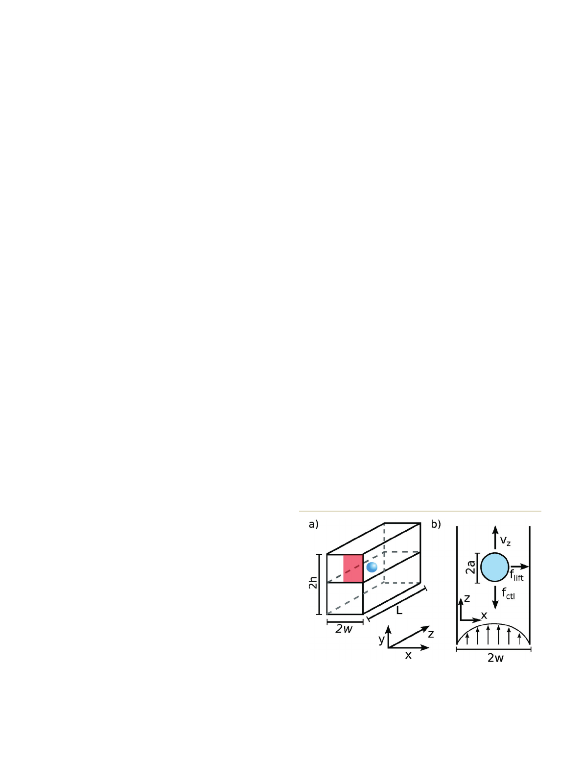
We investigated a microfluidic channel with a rectangular
cross section of height 2h, width 2w, and length Las illus-
trated in Fig. 1. We chose the coordinate system such that
the zaxis coincides with the channel axis and the xand yaxes
define the horizontal and vertical directions in the cross sec-
tion, respectively. The channel center corresponds to x=y=0.
The channel was filled by a Newtonian fluid with density ρ
and kinematic viscosity νand a pressure driven Poiseuille flow
was applied.
12
The maximum flow velocity u
0
at the channel
center determines the Reynolds number Re = 2wu
0
/ν. The
implementation of the Poiseuille flow within the lattice
Boltzmann method will be discussed in the next section.
Inside the channel, we placed a neutrally buoyant colloid
with radius a. It follows the streamlines of the applied
Poiseuille flow with an axial velocity v
z
close the external
Poiseuille flow velocity. Due to the fluid inertia the colloidal
particle experiences a lateral lift force f
lift
, which leads to
cross-streamline migration. In sects. 4 and 5, we also applied
an additional axial control force f
ctl
to the colloidal particle.
We used periodic boundary conditions along the axial direc-
tion and a channel length L=20ato ensure that the periodic
colloidal images do not interact with each other and thereby
do not influence our results.
2.2 The lattice Boltzmann method
We used the lattice Boltzmann method (LBM) to solve the
Navier–Stokes equations of a Newtonian fluid.
27,28
LBM employs
an ensemble of point particles that perform alternating steps of
free streaming and collisions. The particles are constrained to
move on a cubic lattice with a lattice spacing Δx. This restricts
the particle velocities to a discrete set of vectors
cisuch that
after each streaming step with duration Δtthe new particle
positions again lie on the lattice. In LBM, one describes the
Fig. 1 A schematic of the microfluidic channel (a) and the xz plane at
y= 0 (b). Further explanations are given in the main text. It is sufficient
to only determine the inertial lift force f
lift
in the red quadrant due to
the symmetry of the rectangular cross section.
Lab on a ChipPaper
Published on 01 April 2014. Downloaded by TU Berlin - Universitaetsbibl on 24/02/2016 13:55:06.
View Article Online
Lab Chip, 2014, 14, 2115–2123 | 2117This journal is © The Royal Society of Chemistry 2014
number of particles at lattice point
xwith velocity
ciby the
distribution function fxt
i()
. The first two moments of this
distribution function give the hydrodynamic variables: number
density
() ()
xt f xt
i
i
and velocity
uxt cf xt
ii
i
() ,
1
.
Further details of our implementation are found in sect. S1 of
the ESI.†
We implemented the pressure driven Poiseuille flow by
imposing a constant body force
gon the fluid such that the
fluid velocity
uxt()used to calculate the equilibrium distri-
bution f
ieq
(see ESI†) is replaced by
29
uug
(1)
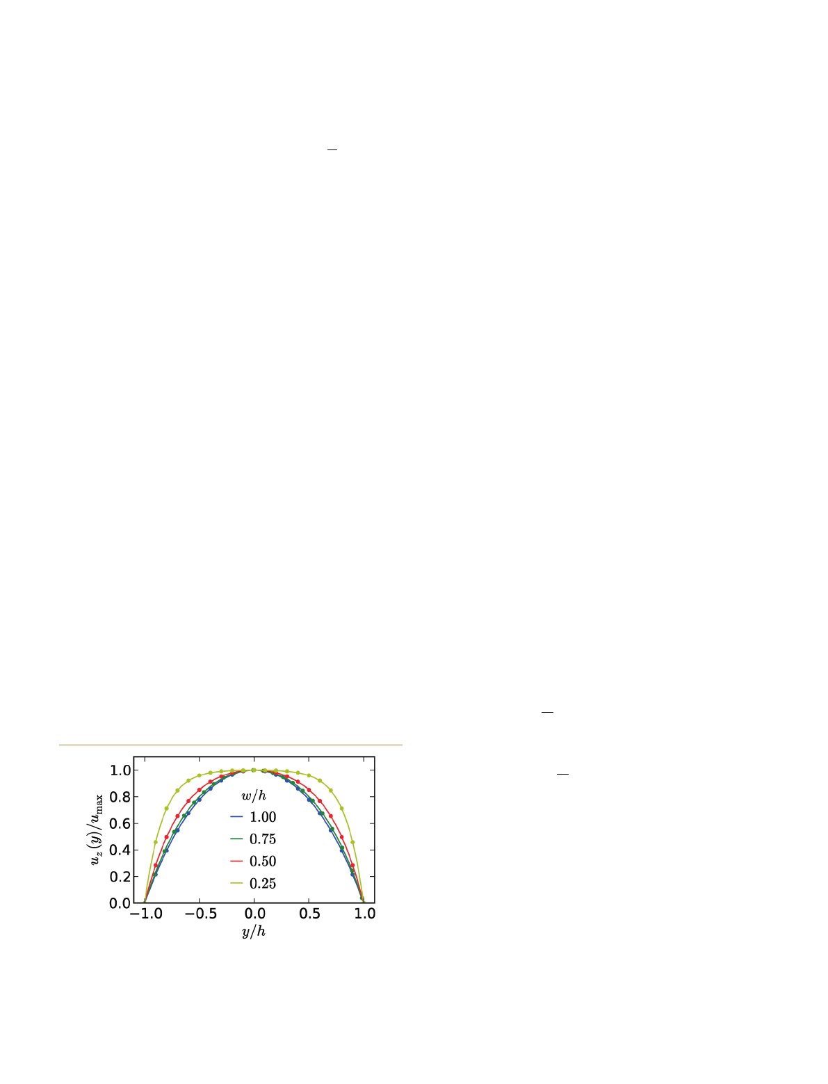
We confirmed as shown in Fig. 2 that this procedure does
indeed reproduce the analytically known Poiseuille flow profile.
We placed a colloid in the Poiseuille flow and studied its
position
r, velocity
v, and angular velocity
. We com-
bined the colloid to the fluid using the Inamuro Immersed
Boundary (IB) method
30
with “five iterations”. For reference,
we presented a short summary of our implementation in
sect. S2 of the ESI.†
We used the palabos LB code
31
to implement the LB algo-
rithm. We modified the immersed boundary (IB) algorithm
to correctly account for the periodic boundary conditions
along the channel axis and implemented the colloid dynam-
ics according to eqn (S9) in the ESI.†
Along the channel width, we used a total of 101 lattice
sites including the boundaries. We implemented a cubic sim-
ulation grid and chose the number of lattice sites in the
other two directions accordingly. We chose the maximum
flow velocity in the channel such that the Mach number sat-
isfies Ma = u
max
/c
s
≤0.1. Finally, we adjusted the kinematic
viscosity by the relaxation time τand thereby fixed the
desired Reynolds number Re = u
max
w/v. When τ>1, we
readjusted the Mach number such that τ= 1, as it has been
shown that the accuracy of the combined LBM-IB methods
greatly decreases for relaxation times larger than one.
32,33
2.3 Determining inertial lift forces
To determine inertial lift forces from LB simulations, we
constrained the colloid to a fixed lateral position by simply
disregarding any colloid motion in the cross-sectional plane.
However, we did not impose any constraints on the axial and
rotational motions.
To speed up our simulations, we initialized the system
with the analytical solution of the rectangular Poiseuille flow
and gave the colloid an initial axial velocity v
z
= 0.8u
0
, where
u
0
is the flow velocity at the channel center. Going through
transient dynamics, the system relaxes rapidly into a unique
steady state within the first 1000 time steps. We continued the
time-evolution up to the vortex diffusion time T= 0.5w
2
/vand
determined the inertial lift force by averaging the colloidal force
fluid
Ffrom eqn (S7) in the ESI†over the last 2000 time steps
of the simulations. We demonstrated in previous studies
15,17
that this procedure does indeed reproduce correct lift-force
profiles.
2.4 Langevin dynamics simulations
As demonstrated below, axial control forces influence the
inertial lift-force profiles which we determined in the LB sim-
ulations. We then used these profiles in Langevin dynamics
simulations of the colloidal motion to investigate the poten-
tial benefit of feedback control using axial control forces.
We restricted ourselves to channels with an aspect ratio
w/h= 1/3, which ensures that the colloidal dynamics essen-
tially takes place in the xz plane as discussed in sect. 3.2. As
we will discuss in sect. 4, the inertial lift force f
lift
and the
axial velocity v
z
depend on the applied axial control force f
ctl
.
We also included thermal noise to exploit the stability of the
fix points of the colloidal motion under feedback control. Fol-
lowing our work in ref. 17, we only included thermal noise
along the lateral direction, as the axial velocities are much
larger than the lateral ones. Then, the Langevin equations of
motion in the lateral and axial directions are given by
d
dlift ctl
txfxf t()() (2)
d
dctl
tzvxf
z
() (3)
where the white noise force has zero mean, 〈η(t)〉= 0, and its
variance obeys the fluctuation–dissipation theorem, 〈η(t)η(t′)〉=
2k
B
Tξδ(t−t′). We solved the Langevin equations using the con-
ventional Euler scheme.
34
The parameters were chosen for a
channel with width 2w=20μm and at temperature T= 300 K.
3. Inertial lift forces for different
channel geometries
In channels with circular cross sections, inertial lift forces
drive colloids to a circular annulus with a radius of about
Fig. 2 Velocity profiles of the Poiseuille flow in the rectangular
channel plotted at x= 0 along the yaxis (the long cross sectional axis)
for different aspect ratios w/h. The solid lines show the analytical form
of the profiles,
12
while the symbols show results of the LB simulations.
Lab on a Chip Paper
Published on 01 April 2014. Downloaded by TU Berlin - Universitaetsbibl on 24/02/2016 13:55:06.
View Article Online
2118 |Lab Chip,2014,14, 2115–2123 This journal is © The Royal Society of Chemistry 2014
half the channel radius. The axial symmetry is reduced in chan-
nels with square or rectangular cross sections and instead of an
annulus, particles accumulate at a discrete set of stable equi-
librium positions.
7
In addition, the system also shows unstable
equilibrium positions, where the lift force also vanishes but
particles migrate away from them upon a small disturbance.
In the following two sections, we will investigate the loca-
tion and the stability of the equilibrium positions for different
particle sizes, Reynolds numbers, and channel geometries.
We will discuss in detail how we can tailor colloidal motion
by varying the aspect ratio of the channel cross section. Due
to symmetry, we can restrict our discussion to the upper right
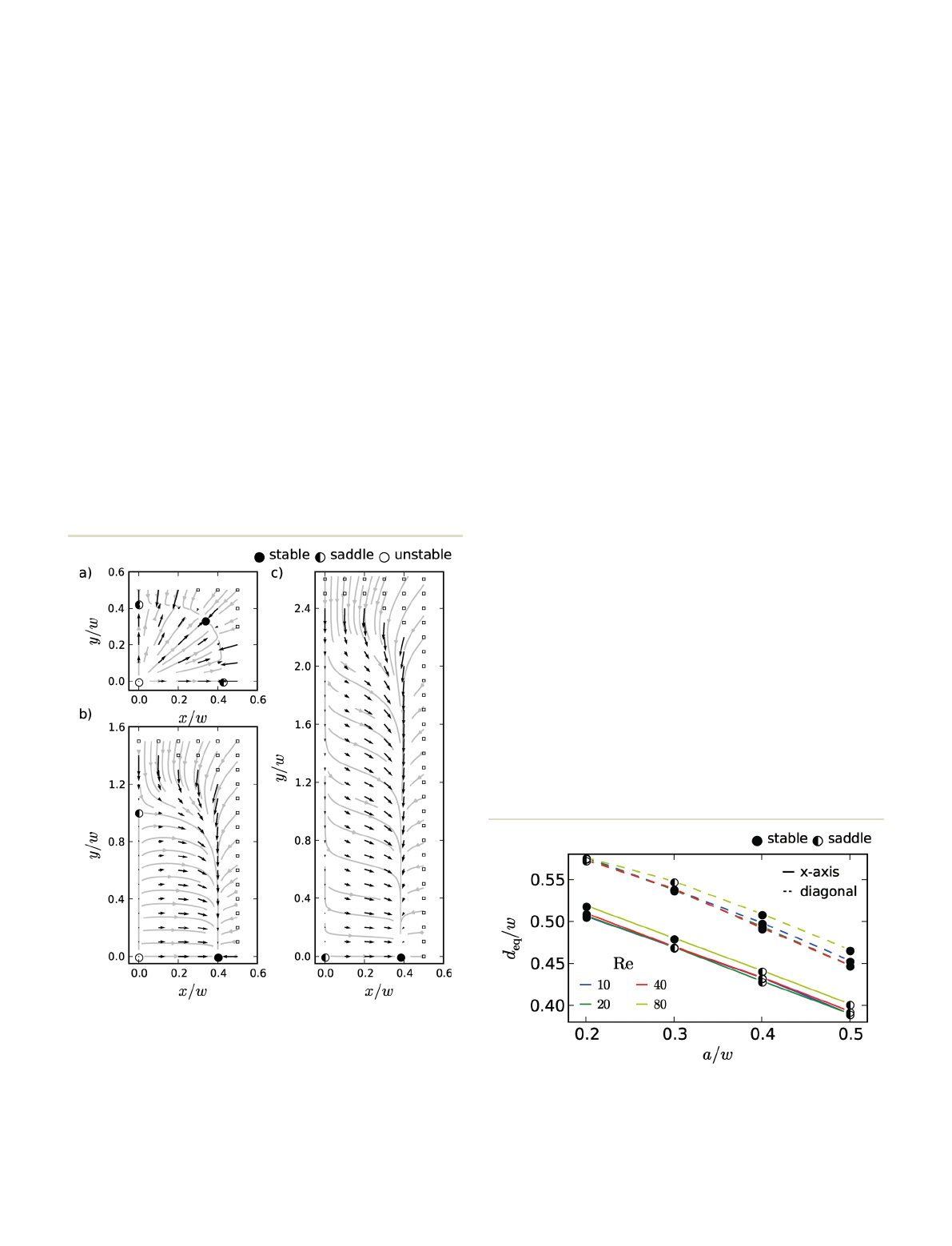
quadrant shown in Fig. 1. In Fig. 3, we show the forces acting
on a particle with radius a/w= 0.4 and the resulting trajecto-
ries at Reynolds number Re = 10 for different channel cross
sections. We will discuss the relevant features first for a chan-
nel with square cross sections and then for general rectangu-
lar cross sections.
3.1 Square channels
In a channel with a square cross section and at Reynolds
number Re = 10, a particle with radius a/w= 0.4 experiences
the inertial force profile shown in Fig. 3(a). The gray lines
indicate possible trajectories followed by the particles, which
are free to migrate. Stable and unstable equilibrium positions
are also indicated. We observed that the migration roughly
occurs in two steps. From the channel center and the chan-
nel walls, strong radial forces drive the particle onto an
almost circular annulus at about r≈0.4w. Since the forces
are strong, migration occurs very rapidly. Then, the particle
slowly migrates along the annulus to its equilibrium position
here situated on the diagonal direction.
Together with the channel center there are in total nine
equilibrium positions or fix points in the channel cross sec-
tion. Four of them are indicated in Fig. 3(a). The channel
center is always unstable and the particle migrates away from
it. There are four fix points along the diagonal axes and four
along the main axes (x,ydirections) of the channel cross
section. We plotted their distances from the center versus
the colloid radius for several Re as shown in Fig. 4 and also
indicated their stability. The fix points along the diagonals are
always positioned further away from the channel center as
there is more space for the particle. Consistent with the previ-
ous results,
6,9,15
we observed how both types of equilibrium
positions move closer towards the channel center with increas-
ing particle size and decreasing Reynolds number. Most impor-
tantly, small particles at high Reynolds numbers have their
stable equilibrium positions on the main axes, while larger
particles at lower Reynolds number move to the equilibrium
positions on the diagonals. This is a new result compared to
previous treatments.
6,8,9
In the literature, equilibrium positions in square channels
have been reported along the main axes,
6
along the diagonals
for large deformable drops
8
or on both axes.
9
In contrast to
ref. 9 we observed that the particles move either to the diago-
nal equilibrium positions or to the fix points on the main
axes but the equilibrium positions are never stable at the
same time as illustrated in Fig. 4. It has been demonstrated
in spiral channels with a trapezoidal cross section
3
that such
Fig. 3 Inertial lift forces (black arrows) of a colloidal particle with
radius a/w= 0.4 in a pressure driven flow at Re = 10. The forces are
plotted in the upper right quadrant of the microchannel cross section
for aspect ratios w/h= 1 (a), w/h= 1/2 (b) and w/h= 1/3 (c). The gray
lines indicate the trajectories of the colloidal particle as it experiences
the lift forces. Lift forces larger than 0.35ρν
2
are not shown, as their
positions are indicated by squares. Also indicated are the stable and
unstable equilibrium positions. With “saddle”we denote the
equilibrium positions unstable only along one direction.
Fig. 4 Equilibrium positions d
eq
(distance from the center) in a square
channel are plotted versus the colloid radius for different Re.
Equilibrium positions exist along the main axis in the x,ydirections
(solid lines) and along the diagonal (dashed line). Closed circles indicate
stable equilibrium positions, whereas open circles are unstable.
Lab on a ChipPaper
Published on 01 April 2014. Downloaded by TU Berlin - Universitaetsbibl on 24/02/2016 13:55:06.
View Article Online
Lab Chip,2014,14, 2115–2123 | 2119This journal is © The Royal Society of Chemistry 2014
a sudden change in stability can be used to efficiently sort
particles by size. We noted that while the particle size is fixed by
the specific system under investigation, the Reynolds number
remains a free parameter and can be used to tune the stability
of the equilibrium positions. Stable equilibrium positions on
the diagonals were not observed in the experiments and finite
element simulations performed by Di Carlo et al.
6
While we
are not aware of any obvious reason how to resolve this discrep-
ancy, we have noted that for channel aspect ratios different
from unity a subtle change from stable diagonal equilibrium
positions towards axial positions occurs as discussed in the
next section. Furthermore, diagonal positions are only stable
for sufficiently large particles.
3.2 Rectangular channels
In the experiments, channels typically with rectangular cross
sections were used since the number of stable equilibrium
positions reduces to two situated on the short main axis.
6
We
observed the same behavior in the force profiles in Fig. 3 for
large colloids, while for channels with a square cross section
a particle migrates to its stable position on the diagonal
[Fig. 3(a)], this fix point vanishes with a decreasing aspect
ratio w/hand the stable equilibrium position switches to the
short main axis along the xdirection [Fig. 3(b)]. Further
decreasing the aspect ratio w/h, the saddle fix point on the
yaxis vanishes completely and moves to the center at x=y=0,
where it keeps its stability along the yaxis [Fig. 3(c)]. This has
an important consequence (already exploited by us
17
) that the
colloid is constrained to the xz plane at y= 0 and its dynamics
becomes two-dimensional. In contrast, in Fig. 3(b), a particle
starting close to the centerline moves out of the y= 0 plane on
its way to the stable equilibrium position at x≈0.4. This is
consistent with the simulations performed by Gossett et al.,
35
where a similar behavior was observed. We will now elaborate
in more detail on these observations.
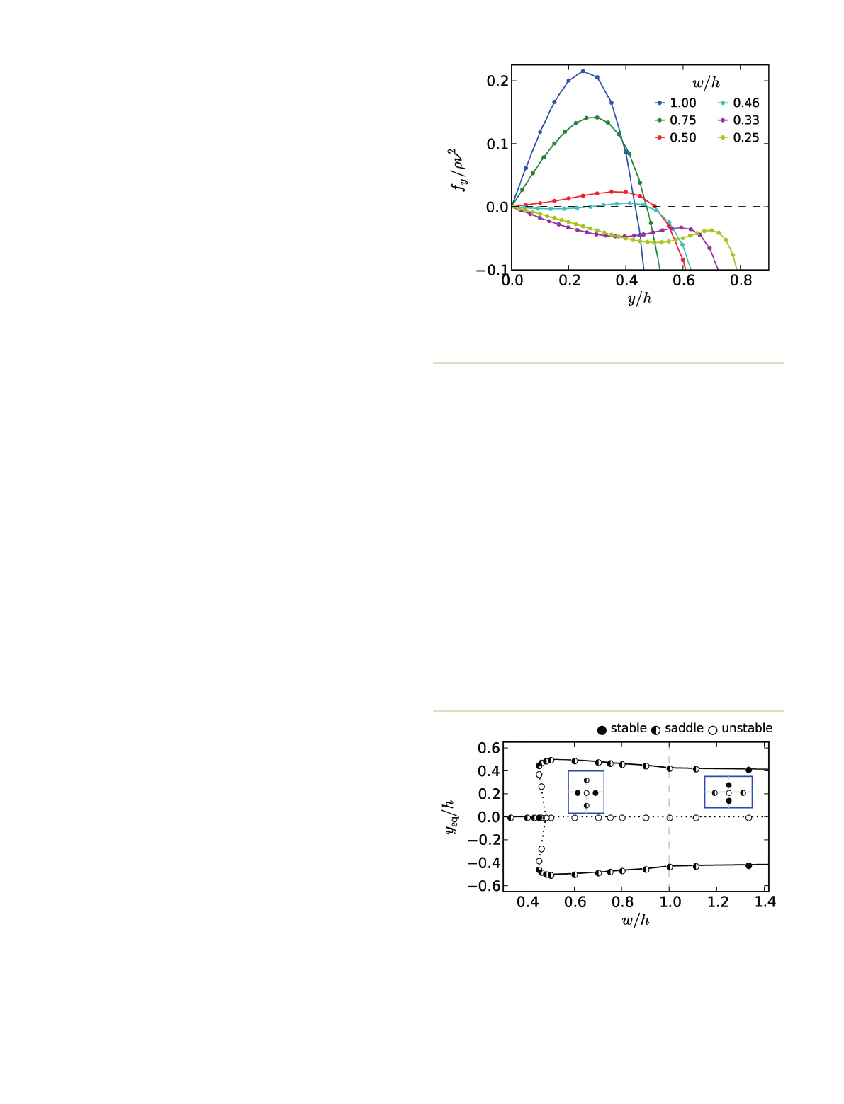
We first plotted the lift force along the yaxis, i.e.,atx= 0 for
several aspect ratios w/has shown in Fig. 5. Due to symmetry,
the lift force always points along the ydirection. For the qua-
dratic cross section, w/h= 1, zero lift forces indicate the unsta-
ble fix point in the center (x=y= 0) and the saddle fix point
at y≈0.42, which is unstable in the xdirection. As the chan-
nel cross section elongates along the ydirection with decreas-
ing w/h, the lift force driving the particle away from the
channel center becomes weaker and the saddle fix point shifts
towards the channel wall. Below the width w≈0.45h, the lift
force close to the center becomes negative and the unstable
fix point at y= 0 splits into a saddle fix point (now stable in
the ydirection) and an additional unstable fix point. While
we did not show this situation in Fig. 3, it qualitatively looks
the same as in the complete force profile in Fig. 9(a) for
smaller colloids. This is the onset, where the channel center
becomes stable against motion along the yaxis and the col-
loid is constrained to the xz plane at y= 0. Further decreas-
ing the aspect ratio w/h, the unstable and saddle fix points at
y≠0 merge and vanish completely. Only the saddle fix point
at x=y= 0 remains as illustrated in Fig. 3(c). Finally, we
noted that at w/h≈0.75 the stable equilibrium position in
the channel cross section switches from the diagonal to the
xaxis, which is not observed in Fig. 5.
We summarized the situation in the bifurcation diagram
in Fig. 6, where we have plotted the equilibrium positions on
the yaxis versus the aspect ratio w/h. At sufficiently small w/h
only the saddle fix point at y= 0 exists [Fig. 3(c)]. With
increasing w/h, subcritical pitchfork bifurcation occurs. A
second fix point appears which splits into the saddle and
unstable fix points [Fig. 9(a)]. The latter ultimately merges
with the fix point at y= 0 which becomes unstable [Fig. 3(b)].
This resulting situation is illustrated in the left inset for the
whole cross section and with the stable fix point on the
xaxis. The stable fix point moves to the diagonal at w/h≥0.75.
The regime of the subcritical pitchfork bifurcation is much
more pronounced for smaller particles as illustrated in the
Fig. 5 Lift force f
y
along the y-direction at x= 0 is plotted versus the
yposition of Re = 10 and a/w= 0.4. The different colors correspond to
different aspect ratios w/h.
Fig. 6 Equilibrium positions along the yaxis are plotted versus the
channel aspect ratio w/hof Re = 10 and colloid radius a/w= 0.4.
The equilibrium positions are categorized as stable, saddle, and
unstable, using also their stability with respect to the xdirection. The
blue insets show typical equilibrium positions in the channel cross
section for w/h<1 (left) and for w/h>1.33 (right).
Lab on a Chip Paper
Published on 01 April 2014. Downloaded by TU Berlin - Universitaetsbibl on 24/02/2016 13:55:06.
View Article Online
Loading more pages...