
This version is available at https://doi.org/10.14279/depositonce-10475
This work is licensed under a CC BY-NC-ND 3.0 License (Creative
Commons Attribution-NonCommercial-NoDerivatives 3.0 International). For
more information see https://creativecommons.org/licenses/by-nc-nd/3.0/.
Terms of Use
This is the Accepted Manuscript version of an article accepted for publication in Semiconductor Science
and Technology. IOP Publishing Ltd is not responsible for any errors or omissions in this version of the
manuscript or any version derived from it. The Version of Record is available online at
https://doi.org/10.1088/1361-6641/ab1c06.
Greif, L. A. T., Mittelstädt, A., Jagsch, S. T., & Schliwa, A. (2019). Twofold gain enhancement by
elongation of QDs in polarization preserving QD-SOAs. Semiconductor Science and Technology, 34(7),
075003. https://doi.org/10.1088/1361-6641/ab1c06
Ludwig A. Th. Greif, Alexander Mittelstädt, Stefan T. Jagsch, Andrei
Schliwa
Twofold gain enhancement by elongation
of QDs in polarization preservin
g
QD-SOAs
Accepted manuscript (Postprint)Journal article |

Semiconductor Science and Technology
ACCEPTED MANUSCRIPT
Twofold gain enhancement by elongation of QDs in polarization
preserving QD-SOAs
To cite this article before publication: Ludwig A. Th. Greif et al 2019 Semicond. Sci. Technol. in press https://doi.org/10.1088/1361-6641/ab1c06
Manuscript version: Accepted Manuscript
Accepted Manuscript is “the version of the article accepted for publication including all changes made as a result of the peer review process,
and which may also include the addition to the article by IOP Publishing of a header, an article ID, a cover sheet and/or an ‘Accepted
Manuscript’ watermark, but excluding any other editing, typesetting or other changes made by IOP Publishing and/or its licensors”
This Accepted Manuscript is © 2019 IOP Publishing Ltd.
During the embargo period (the 12 month period from the publication of the Version of Record of this article), the Accepted Manuscript is fully
protected by copyright and cannot be reused or reposted elsewhere.
As the Version of Record of this article is going to be / has been published on a subscription basis, this Accepted Manuscript is available for reuse
under a CC BY-NC-ND 3.0 licence after the 12 month embargo period.
After the embargo period, everyone is permitted to use copy and redistribute this article for non-commercial purposes only, provided that they
adhere to all the terms of the licence https://creativecommons.org/licences/by-nc-nd/3.0
Although reasonable endeavours have been taken to obtain all necessary permissions from third parties to include their copyrighted content
within this article, their full citation and copyright line may not be present in this Accepted Manuscript version. Before using any content from this
article, please refer to the Version of Record on IOPscience once published for full citation and copyright details, as permissions will likely be
required. All third party content is fully copyright protected, unless specifically stated otherwise in the figure caption in the Version of Record.
View the article online for updates and enhancements.
This content was downloaded from IP address 130.237.165.40 on 30/04/2019 at 07:03
Twofold Gain Enhancement by Elongation of
QDs in Polarization Preserving QD-SOAs
L A Th Greif,∗A Mittelstädt, S T Jagsch, and A Schliwa
Technische Universität Berlin, Institut für Festkörperphysik, Hardenbergstraße 36, 10623
Berlin, Germany
E-mail: [email protected]berlin.de
Abstract
The impact of quantum dot(QD) elongation
on key parameters of QD-based semiconductor
optical amplifiers(SOAs) is investigated using
a combination of 8-band k·p-theory including
strain and piezoelectricity up to second order
and a rate equation model describing the popu-
lation of QD ground, excited and wetting layer
states. By considering columnar QDs of se-
lected aspect ratios, we show that chip gain
and saturation gain can be enhanced by up to
+3.6dB via an increased elongation of the in-
dividual QDs while retaining polarization pre-
serving amplification and gain recovery times
below 700fs. Our results enable the optimiza-
tion of polarization preserving QD-SOA devices
which combine ultrafast gain recovery with high
gain and low power consumption.
Keywords
self-assembled quantum dots, semiconductor
optical amplifier, k·p-theory, gain enhance-
ment
1 Introduction
Since the first pioneering works predicted most
desirable electronic and dynamic properties for
quantum dots(QDs),1,2 they have been in the
focus of research for use in semiconductor op-
tical amplifiers(SOAs). Ultrafast gain recovery
and pronounced nonlinear effects3substantiate
the high potential of QD-SOAs in the fields
of high frequency signal amplification, all-op-
tical data processing and wavelength conver-
sion using four-wave-mixing(FWM)4–7. De-
vices with modulation frequencies exceeding
200GHz8and a 120nm broadband gain with
saturation output powers above 20dB facil-
itate wavelength division multiplexing9,10and
high efficiency symmetric FWM.11 Further-
more, several experimental and theoretical
works have shown that, using closely stacked
QDs, polarization preserving amplification can
be realized.12–18 A remaining drawback is the
lower chip gain of QD-SOAs when compared to
quantum well-based systems, requiring longer
or multiple gain devisions to achieve compara-
ble amplification.9
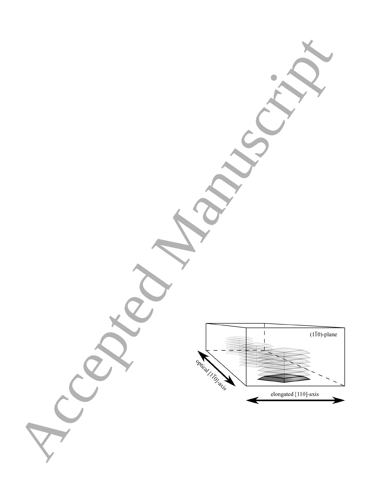
elongated [110]-axis
optical [110]-axis
Figure 1: Scheme of the active region of a QD-
SOA with closely stacked QDs, showing the axis
of elongation with respect to the optical axis.
In this paper, we study an approach to in-
1
Page 1 of 12 AUTHOR SUBMITTED MANUSCRIPT - SST-105492.R1
1
2
3
4
5
6
7
8
9
10
11
12
13
14
15
16
17
18
19
20
21
22
23
24
25
26
27
28
29
30
31
32
33
34
35
36
37
38
39
40
41
42
43
44
45
46
47
48
49
50
51
52
53
54
55
56
57
58
59
60
Accepted Manuscript
crease the chip gain of a QD-SOA while simul-
taneously preserving the input signal polariza-
tion. The gain enhancement is realized using
c-plane QDs that are elongated perpendicular
to the optical [1¯
10]-axis of the device (figure 1).
Several growth studies have demonstrated that
such elongated QDs can be realized with molec-
ular beam epitaxy(MBE) as well as metalor-
ganic vapor phase epitaxy(MOVPE) via ad-
justing the growth temperature or including an-
nealing steps.19–21 However, the formation of a
uniform elongation of all QDs within one stack
is still challenging.22
Due to the asymmetric confinement in the
(001)-plane the QD ground state transition
dipole moment is rotated into the (1¯
10)-plane,
optimizing the alignment with the electric field
of the optical signal. Thereby, the polarization
of the amplified signal is preserved in the (1¯
10)-
plane. The results are not limited to this unique
configuration of optical axis and QD-axis but
can be generalized as long as the axis of elonga-
tion is orientated perpendicular to the optical
axis of the QD-SOA.
Anisotropic transition dipole moments caused
by anisotropic nanostructures were already
used in InAs/InP quantum dash lasers and
SOAs.23–25 Quantum dashes represent an in-
termediate structure between QDs and quan-
tum wires with at least one dimension sig-
nificantly exceeding the exciton Bohr radius
and thus exhibit only two-dimensional quantum
confinement.26 Due to the bigger volume com-
pared to QDs, the threshold current is usually
slightly higher than in QD based structures27
and although polarization insensitive amplifica-
tion seems achievable28 to our best knowledge
it has not been demonstrated so far.
The paper is organized as follows. After intro-
ducing the device structure, a brief paragraph
discusses the method for calculating the spa-
tially resolved radiation intensities of a stack
of QDs. QD stacks with a vanishing degree of
polarization(DOP) in the (1¯
10)-plane are then
calculated for five different horizontal aspect ra-
tios ARh=d[110]/d[1¯
10](elongations), where di
is the length of the diagonal [i] in the basis
plane. Subsequently, the results are used to de-
termine the impact of the QD elongation on the
stimulated emission rate as well as other key
properties of the QD-SOA, such as chip gain,
saturation gain and gain recovery time(GRT).
2 Structure Details
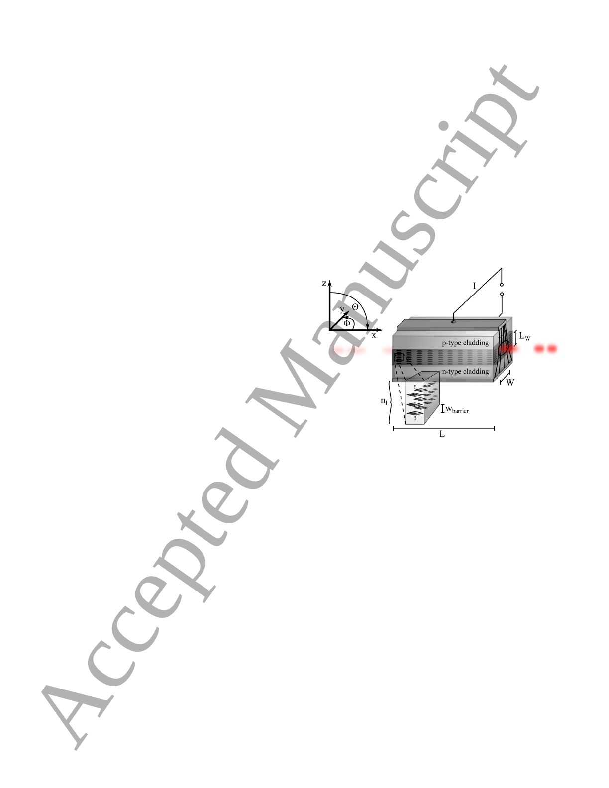
Typical QD-SOA designs use the tilted ridge
waveguide geometry,5,29,30 where the cross sec-
tion provides refractive index nguiding along
the vertical and gain guiding in lateral direc-
tion (figure 2). Following Jayavel et al.,31 we
use Al0.5Ga0.5As for the cladding (n= 3.1) and
GaAs (n= 3.3) as matrix material in order to
realize the index guiding.
Figure 2: Schematic QD-SOA with pump cur-
rent I, a resulting current injection region of
width W, height of the active region LW, cav-
ity length Land nllayers of quantum dots, each
separated by a barrier of width wbarrier.
Figure 2 shows the active region composed
of seven layers of closely stacked QDs aligned
along the c-axis. The QDs are placed on a two-
monolayer(ML)-thick wetting layer (included
in the QD height). The barrier width wbarrier is
set to zero ML, as experimental findings suggest
that columnar QDs stay in contact with each
other along the growth direction.12,14,15 The in-
dividual QDs are modeled as truncated InAs-
pyramids with a side-wall angle of 30◦and di-
mensions given in table 1.
As shown in [13,32,33], elongation affects the
polarization properties of single and stacked
QDs. Thus, when changing the QD elongation,
2
Page 2 of 12AUTHOR SUBMITTED MANUSCRIPT - SST-105492.R1
1
2
3
4
5
6
7
8
9
10
11
12
13
14
15
16
17
18
19
20
21
22
23
24
25
26
27
28
29
30
31
32
33
34
35
36
37
38
39
40
41
42
43
44
45
46
47
48
49
50
51
52
53
54
55
56
57
58
59
60
Accepted Manuscript

Table 1: Geometric specifications of the indi-
vidual QDs.
ARhQD height d[110] [nm]
1.0 1.13 12.39
1.5 1.13 11.19
2.0 1.41 12.39
2.5 1.70 12.39
3.0 1.13 7.59
adjustments in the geometry of the individual
QDs are necessary to preserve polarization in-
sensitivity of the stacks. Differences in the QD
volume are of no particular significance as only
the spatial radiation pattern enters the subse-
quent simulations of the QD-SOA dynamics as
discussed in section 3.2.
Device and operational parameters are
adapted from [34,35] and listed in table 2.
3 Method of Calculation
In order to connect macroscopic device prop-
erties like electric current and photon density
with the elongation of the zero dimensional
QDs, we use the rate equation model described
in [34–37] accompanied by numerically obtained
QD emission characteristics. In a first step, the
radiation pattern of the QD stacks with differ-
ent elongations are calculated using an 8-band
k·p-model including strain and strain-induced
piezoelectricity.38,39 Subsequently, the radiation
pattern is used to determine the ratio of pho-
tons spontaneously emitted into the waveguide,
known as β-factor
β=# spon. emitted along the waveguide
# all spon. emitted .
(1)
This figure of merit enters the rate equation
model and allows us to qualitatively study the
impact of the QD elongation on the device prop-
erties via its influence on the electron and hole
wavefunctions.
3.1 Beta-Factor and Spontaneous
Emission Rate
In order to obtain the rate of photons emitted
by the QDs within the waveguide structure, we
use Fermi’s golden rule
Γi→f()∝ |· hf|∇|ii |2.(2)
The polarization dependent transition rate
Γi→f()can be derived with the help of the 8-
band k·pelectron and hole wavefunctions |fi
and |ii, respectively. Following [40], Γi→f()
is transformed into a function of the propaga-
tion direction k. Only photons whose propa-
gation direction k(φk, θk)fulfills the following
equations41 are confined within the waveguide
θk≤arccos ˆn2
ˆn1=θlim,(3)
φk≤arctan W
2(L−x)=φlim.(4)
Here, ˆn1,ˆn2are the refractive index of the ma-
trix and cladding material, respectively, Wis
the width of the injection region, Lis the SOA
length and xis the position in the SOA along
the optical axis. We eliminate the spatial de-
pendence of (4) by averaging the limit angle
φlim over the active region
¯
φlim =1
LZL
0
dx φlim(x).(5)
With the help of the calculated limit angles, the
β-factor can be derived as the ratio of the sum
of all photons emitted within the limit angles
to the total sum of emitted photons.
3.2 Rate Equation Model
The rate equation model is adapted from
[34,35,37] with corrections suggested by Li and
Li in [36]. The model describes the temporal
evolution of the charge carrier densities within
the wetting layer NW, the QD excited state
N2=˜
NQn2and ground state N1=˜
NQn1.
Here, n2and n1are the occupation proba-
bilities of excited state and ground state, re-
spectively. Occupation probabilities and carrier
3
Page 3 of 12 AUTHOR SUBMITTED MANUSCRIPT - SST-105492.R1
1
2
3
4
5
6
7
8
9
10
11
12
13
14
15
16
17
18
19
20
21
22
23
24
25
26
27
28
29
30
31
32
33
34
35
36
37
38
39
40
41
42
43
44
45
46
47
48
49
50
51
52
53
54
55
56
57
58
59
60
Accepted Manuscript
Loading more pages...