
Chapter 3: Thermally Driven Heat Pumps for Heating
_______________________________________________________________________________________________________________________________________________________________________________________________________________________________________________________________________________________________________________________________________________________________________________________________________________________
63
ANALYSIS OF A GAS-DRIVEN ABSORPTION HEAT PUMPING
SYSTEM USED FOR HEATING AND DOMESTIC HOT WATER
PREPARATION
Harald Moser, Rene Rieberer, Graz University of Technology, Institute of Thermal
Engineering, Inffeldgasse 25 B, A-8010 Graz, Austria, rene.rieberer@tugraz.at
This paper was published in the proceedings of the 10th International Heat Pump Conference 2011
(www.heatpumpcentre.org/en/hppactivities/ieaheatpumpconference).
Abstract: In the building sector the use of thermally driven heat pumps can contribute
substantially to energy conservation and the reduction of end-use energy. Within the IEA
HPP Annex 34 a medium size absorption heat pump application installed in a storehouse in
Graz has been monitored over a period of one year.
The system consists of two directly natural gas-driven ground source ammonia/water
absorption heat pumps (each with ca. 40 kW heating capacity). Via a buffer storage space
heating of an office building and a storage depot as well as domestic hot water preparation is
provided.
During the monitoring period the system showed reliable operation and high energy
performance. Based on the lower heating value of the natural gas the seasonal performance
of the year 2010 was 1.54 which is approx. 60% higher compared to a condensing gas boiler
with a seasonal performance of 96%. However, also room for improvements has been
detected, especially at start/stop operation for domestic hot water preparation in summer.
Key Words: demonstration project, monitoring, IEA HPP Annex 34, ground source
1 INTRODUCTION
In the building sector the use of natural gas driven absorption heat pumps can contribute
substantially to energy conservation and the reduction of CO2-emmisions due to the
reduction of the end-use energy demand. Especially the small-capacity range of absorption
heat pumps for heating purpose are commonly considered as the logical next development
step beyond the condensing gas boiler and thus the market potential is enormous. However,
small-capacity applications still suffer from relatively low efficiencies and/or high investment
cost compared to other technologies.
In the medium capacity range of around 50 kW heating capacity several absorption heat
pumps are available on the market. Large scale AHP for heating purpose are relatively rare
and mainly special designed systems based on chillers are used (Ziegler 2002).
The Annex 34 “Thermally Driven Heat Pumps for Heating and Cooling” within the IEA “Heat
Pump Program” (HPP) aims to the reduction of the environmental impact of heating and
cooling systems by the use of thermally driven heat pumps. One of the main objectives of the
Annex 34 is to quantify the economic, environmental, and energy performance of integrated
thermally driven heat pumps in cooling and heating systems in a range of climates, countries,
and applications. Within this framework at Graz University of Technology (Institute of
Thermal Engineering) a demonstration project has been started. The aim of the project is to
Chapter 3: Thermally Driven Heat Pumps for Heating
_______________________________________________________________________________________________________________________________________________________________________________________________________________________________________________________________________________________________________________________________________________________________________________________________________________________
64
evaluate the seasonal performance of two ammonia/water absorption heat pumps for heating
and domestic hot water preparation.
2 APPLICATION DATA
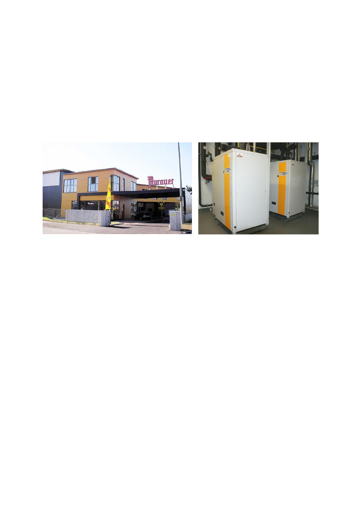
Two “Helioplus 40-S” absorption heat pumps from the company “Helioplus Energy Systems
GmbH” are installed in a storehouse of a brewery in Graz, Austria (compare Figure 1 and
Figure 2). These ammonia/water AHP are directly driven by natural gas, have a maximum
supply temperature of 60°C and a heating capacity of 37.1 kW each. One feature of these
AHP is that they include also a flue gas heat exchanger in order to condense water in the
flue gas by rejecting condensing heat directly to the return flow of the heating circuit.
Figure 1: Storehouse building where the AHPs are
installed
Figure 2: Photo of AHP installation
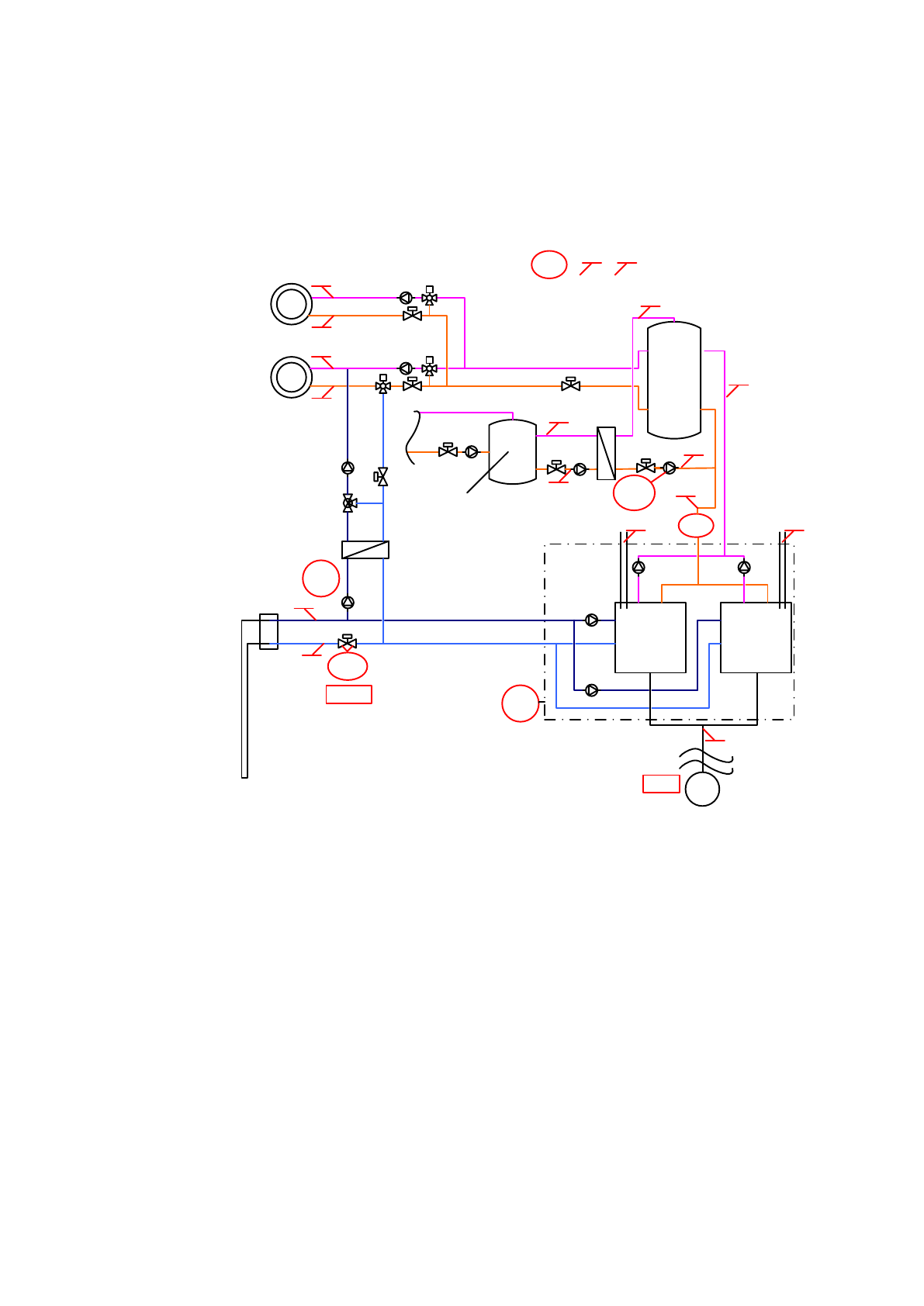
The AHP supply heat to a 1.2 m³ stratified thermal water storage tank (compare Figure 3).
This storage tank supplies heating water to both the space heating distribution system and
the domestic hot water tank. The outlet nozzle for the space heating system is located at an
intermediate level and for domestic hot water preparation at the very top in order to receive
the required temperature level.
The heating area comprises of an approx. 2000 m² storage depot and an office area with
approx. 600 m². The storage depot has a nominal heating capacity of ca. 57 kW and is
heated to 18°C. The office has a heating capacity of ca. 19 kW and is heated to 22°C room
temperature. For domestic hot water (DHW) preparation a 0.5 m³ storage tank is used. It is
charged by the heat from the heating water storage tank via a plate heat exchanger.
For space heating the heating water storage is controlled with respect to the ambient
temperature and heating curve in order to achieve a temperature level in the storage approx.
2 K in excess of the required supply temperature (ca. 40°C at -12°C ambient temperature) for
the heat distribution system.
If the temperature level of the DHW tank drops below a certain threshold the control of the
AHP is switched to the DHW temperature set point in order to heat the upper part of the
heating water storage to the required temperature level of more than 50°C. Using this
heating water the domestic hot water tank is charged via a plate heat exchanger. After the
temperature level of the domestic hot water tank has reached the temperature set point of
50°C the control of the AHP is switched back to the current space heating temperature set
point.
Chapter 3: Thermally Driven Heat Pumps for Heating
_______________________________________________________________________________________________________________________________________________________________________________________________________________________________________________________________________________________________________________________________________________________________________________________________________________________
65
The low temperature energy source for the AHP is provided by 7 ground probes each with a
length of 100 m and a mixture of water and propylene glycol (ca. 20 wt%) is used as heat
carrier. During summer the ground probes are used for free cooling of the office area.
Therefore a plate heat exchanger is used in order to reject the heat from the heating water to
the heat carrier of the ground probes. However, free cooling operation is not discussed in this
paper and active cooling by the AHP is not provided.
GAS
AHP 1
GAS
AHP 2
Gas
Ground
Domestic
Hot Water
0,5 m³
Heating
Water
1,2 m³
WAHP
VAHP
DpESC
Ground
Probes
Free Cooling-
Secondary
Circuit
VESC
Free Cooling
Primary Circuit
TESC,in
TESC,out
TAHP,in
TDHW,out
TDHW,in
TAHP,out
WDHW
WFRC
TGAS,in
THW2,in
THW2,out
THW1,in
THW1,out
TFLG,2
TFLG,1
TENV TROM
VGAS
Heating Storage Depot
57,2 kW nom. capacity
Heating Office: 19,2 kW
Free Cooling Office: 9,5 kW
TDWS,out
TDWS,in
pENV
Figure 3: Schematic drawing of the heating system including measurement instrumentation
(for legend symbols see Nomenclature)
3 MONITORING CONCEPT
The system has been monitored from 28.12.2009 until 03.01.2011 using a data logger (type
“e.reader”) and all relevant data have been measured, processed and recorded within a
measurement interval of 10 seconds. Due to some problems with the data transfer within the
time period of week 17 to 19 and 23 to 25 the data sets are incomplete for these weeks.
However, all available data have been used for system evaluation.
3.1 Measurement Instrumentation
The measurement instrumentation contains all relevant temperatures, the energy input of the
heat source, natural gas and the electricity consumption as well as the delivered heat to the
heating water storage tank. The measurement instrumentation is also indicated in the
schematic drawing in Figure 3.

Chapter 3: Thermally Driven Heat Pumps for Heating
_______________________________________________________________________________________________________________________________________________________________________________________________________________________________________________________________________________________________________________________________________________________________________________________________________________________
66
For the natural gas measurement a bellows-type gas flow meter is installed outside the
building. In order to calculate the energy input of natural gas Eq. 1 and Eq. 2 have been
used. For this the average upper heating value (HvGAS) was assumed to be 11.176 kWh/Nm³
(AGGM, 2011) as derived from the gas supplier (average HvGAS value for the period Jan. to
Apr. and Sep. to Dec 2010). The ambient pressure has been measured and the gas pressure
(pGAS) has been assumed to be 22 mbar above the ambient pressure as controlled by the
pressure reducing regulator upstream the gas flow meter. The standard pressure (pNORM) is
1.013 bara, the standard temperature (TNORM) is 0°C. Because exact measurement of the gas
temperature was not possible a temperature of 6°C has been assumed as it is also used for
the gas billing procedure.
NORM,GASGASGAS VHvQ
(1)
NORM
GAS
GAS
NORM
GASNORM,GAS p
p
T
T
VV
(2)
The heat coming from the ground probes have been calculated using Eq. 3 and Eq. 4. Due to
the fact that the system was already installed and in operation when monitoring was decided
within the IEA Annex 34 it was not permitted to insert flow meters in the hydraulic lines. That
is why the volume flow has been measured indirectly by measuring the pressure loss via a
balancing valve (compare Eq. 4).
)TT(cpVQ in,ESCout,ESCESCESCESCESC
(3)
1000
p
3600
Kv
VESC
ESC
ESC
ESC
(4)
The flow coefficient (KvESC = 19.31 m³/h) of the balancing value has been determined on site
using an ultrasonic flow meter. For calculation of the density and specific isobaric heat
capacity a temperature depended polynomial curve fitting of the thermodynamic data has
been used.
Electricity meters have been used for the electrical energy input to the AHP (which
comprises of the heating water pumps, energy source pumps and AHP control), the pump for
domestic hot water preparation and the pump for the primary free cooling circuit. The
electrically consumption of the pumps for the heat distribution system have not been
measured.
In the return flow line of the AHP heating water circuit a heat meter is installed which gives
the possibility to use it as volume flow counter. Using this flow counter the heat output of the
AHP has been calculated acc. to Eq. 5 for each measurement interval.
)TT(cpVQ in,AHPout,AHPAHPAHPAHPAHP
(5)
All temperatures have been measured using PT100 sensors or thermocouples. In order to
analyse the efficiency of the absorption heat pump the weekly Coefficient of Performance for
heating (COPH) has been calculated as indicated in Eq. 6. In order to analyse the absorbed
energy from the energy source additional the COP for cooling (COPC) has been calculated
using Eq. 7.
AHPGAS
AHP
HWQ
Q
COP
(6)

Chapter 3: Thermally Driven Heat Pumps for Heating
_______________________________________________________________________________________________________________________________________________________________________________________________________________________________________________________________________________________________________________________________________________________________________________________________________________________
67
AHPGAS
ESC
CWQ
Q
COP
(7)
3.2 Estimation of Measurement Uncertainties
In order to evaluate the combined standard uncertainties of the calculated heat flows and
COP values the individual uncertainties of the measurement instrumentation have been
estimated and combined by Gaussian error propagation as shown in Eq. 8 (ISO 1995).
i
x
2
2
N
ii
yu
x
f
u
(8)
For the natural gas energy consumption the measurement uncertainty of approx.
0.3 kWh/Nm³ has been estimated which correspond to the individual uncertainties given in
Table 1.
Table 1: Estimated uncertainty for calculation of u(QGAS)
u(HvGAS)
u(VGAS)
u(TGAS)
u(pENV)
[MJ/Nm³]
[%]
[K]
[bar]
0.54
1
4
0.02
The measurement uncertainty for the low temperature heat source (QESC), the delivered heat
of the AHP (QAHP) and the electrical energy input (WAHP) has been calculated for each
measurement interval using the individual measurement uncertainties as given in Table 2.
Table 2: Estimated measurement uncertainty for calculation of u(QESC), u(QAHP) and u(WAHP)
u(cpESC)
u(mESC)
u(TESC,out)
u(TESC,in)
u(cpAHP)
u(mAHP)
u( TAHP)
u(WAHP)
[kJ/kg K]
[kg/h]
[K]
[K]
[kJ/kg K]
[%]
[K]
[%]
0.05
350
0.1
0.1
0.02
1.5
0.4
1
It should be noted, that the temperature sensors of the low temperature heat source have
been wet installed through drain nozzles, thus the process temperatures could be measured
quite accurately. Unfortunately this was not possible at the heating water pipes of the AHP,
thus these temperature sensors have been installed on the outside surface of the pipes.
Subsequently these piping sections have been well insulated in order to limit the effect of the
ambient air temperature. However, the measured temperature possibly deviates from the
process temperature, especially at transient operating conditions. Because the temperature
difference ( TAHP=TAHP,out-TAHP,in) which is relevant for calculation of the capacity can be
measured with higher accuracy this difference has been used for uncertainty propagation.
For all data sets of every week the uncertainties of the COP have been calculated acc. to Eq. 9
and Eq.10.
AHPGASAHP
AHP,H W
2
2
2
AHPGAS
AHP
Q
2
2
2
AHPGAS
AHP
Q
2
2
AHPGAS
COP u
)WQ(
Q
u
)WQ(
Q
u
WQ
1
u
(9)
AHPGASESC
AHP,C W
2
2
2
AHPGAS
ESC
Q
2
2
2
AHPGAS
ESC
Q
2
2
AHPGAS
COP u
)WQ(
Q
u
)WQ(
Q
u
WQ
1
u
(10)
Loading more pages...