
Citation: Geng, S.; Schulte, T.; Maas,
J. Model-Based Analysis of Different
Equivalent Consumption
Minimization Strategies for a Plug-In
Hybrid Electric Vehicle. Appl. Sci.
2022,12, 2905. https://doi.org/
10.3390/app12062905
Academic Editor: Daniela Anna
Misul
Received: 14 February 2022
Accepted: 8 March 2022
Published: 11 March 2022
Publisher’s Note: MDPI stays neutral
with regard to jurisdictional claims in
published maps and institutional affil-
iations.
Copyright: © 2022 by the authors.
Licensee MDPI, Basel, Switzerland.
This article is an open access article
distributed under the terms and
conditions of the Creative Commons
Attribution (CC BY) license (https://
creativecommons.org/licenses/by/
4.0/).
applied
sciences
Article
Model-Based Analysis of Different Equivalent Consumption
Minimization Strategies for a Plug-In Hybrid Electric Vehicle
Stefan Geng 1,2,*, Thomas Schulte 1and Jürgen Maas 2
1iFE—Institute for Energy Research, OWL University of Applied Sciences and Arts, Campusallee 12,
2Mechatronic Systems Laboratory, Faculty of Mechanical Engineering and Transport Systems,
*Correspondence: [email protected]
Abstract:
Plug-in hybrid electric vehicles (PHEVs) are developed to reduce fuel consumption and the
emission of carbon dioxide. Common powertrain configurations of PHEVs (i.e., the configuration of
the combustion engine, electric motor, and transmission) can be operated either in series, parallel,
or power split hybrid mode, whereas powertrain configurations with multimode transmissions
enable switching between those modes during vehicle operation. Hence, depending on the current
operation state of the vehicle, the most appropriate mode in terms efficiency can be selected. This,
however, requires an operating strategy, which controls the mode selection as well as the torque
distribution between the combustion engine and electric motor with the aim of optimal battery
depletion and minimal fuel consumption. A well-known approach is the equivalent consumption
minimization strategy (ECMS). It can be applied by using optimizations based on a prediction of the
future driving behavior. Since the outcome of the ECMS depends on the quality of this prediction,
it is crucial to know how accurate the predictions must be in order to obtain acceptable results.
In this contribution, various prediction methods and real-time capable ECMS implementations are
analyzed and compared in terms of the achievable fuel economy. The basis for the analysis is a holistic
model of a state-of-the-art PHEV powertrain configuration, comprising the multimode transmission,
corresponding powertrain components, and representative real-world driving data.
Keywords: PHEV; ECMS; multimode transmission; optimization; powertrain modeling
1. Introduction
Today, vehicle manufacturers are forced to reduce the fuel consumption of their
products because of enhanced environmental regulations. A promising solution is the
development of plug-in hybrid electric vehicles (PHEV), as they combine an extended
electric cruising range and the possibility of propelling the vehicle by an internal com-
bustion engine (ICE) when the battery is depleted or when high performance is required.
Common powertrain configurations of PHEVs are the series, parallel, and power split
configurations. The efficiencies of these configurations vary depending on the distance and
the power demand of the intended trip [
1
]. Increased efficiency can be obtained by using
so-called multimode or dedicated hybrid transmissions (DHTs). This type of transmission
enables switching between different powertrain configurations during vehicle operation
and combining the individual advantages of these configurations. A general property of a
DHT is that the electric motors are an integral and indispensable part of the transmission [
2
],
which is the case when only the electric motor is able to propel the vehicle in a certain speed
range. Since the part of the transmission for the ICE can be designed for the remaining
and, in general, smaller speed range, a DHT requires fewer speeds and is less complex in
comparison with a conventional automatic transmission. This saves a part of the additional
weight and installation space caused by the electrification of the vehicle. Examples of
available PHEVs equipped with a DHT can be found in [3–7].
Appl. Sci. 2022,12, 2905. https://doi.org/10.3390/app12062905 https://www.mdpi.com/journal/applsci
Appl. Sci. 2022,12, 2905 2 of 17
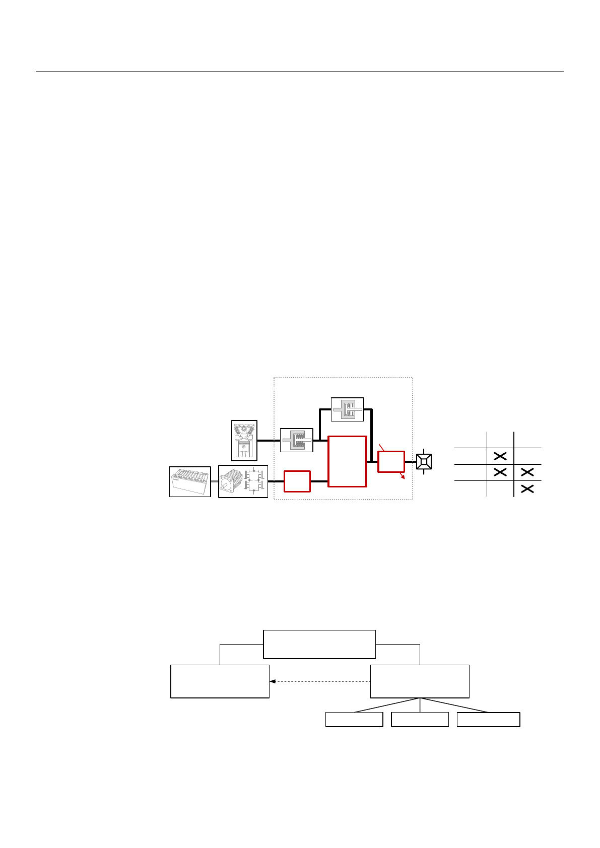
Figure 1shows the basic concept of a hybrid electric powertrain with a DHT, which is
abstractly considered a configuration of two clutches (C), a transmission (T) with a constant
gear ratio
iED
, a planetary gear (PG) with a stationary gear ratio
i0
, and a two-speed
transmission (2ST) with the gear ratios
i1/2
. The concept requires only one electric drive
and enables a continuous variable transmission mode (CVT), a parallel hybrid mode (PAR),
and an electric driving mode (EM), where each mode can be driven in two speeds due to the
two-speed transmission at the output. Clutch C
1
connects the ICE to the DHT, and clutch
C
2
blocks the planetary gear (i.e., all shafts of the planetary gear rotate with the same speed).
In this case, the speed ratios between the transmission’s output and the two input shafts
are constant and depend on the state of C
1
when either the parallel hybrid or the electric
driving mode are active. Due to the chosen transmission ratios, the parallel hybrid mode
can only be driven at higher vehicle speeds. Otherwise, the rotational speed of the ICE will
fall below its lower limit, and the engine will stall. To operate the vehicle at lower speeds,
the electric driving mode or, if the battery is discharged, the CVT mode must be activated.
In this mode, the rotational speeds of the ICE and electric motor are superimposed by a
planetary gear, whereby the speed of the ICE can be adjusted continuously as a function of
the speed of the electric motor and the final drive. The design of the transmission ratios
ensures that the electric motor operates as a generator in CVT mode until an appropriate
vehicle speed is reached. A more detailed description can be found in a previous work [
8
],
where the basic concept was used for the development of a new DHT including a specific
configuration of gears and clutches and the corresponding transmission ratios.
Appl. Sci. 2022, 12, x FOR PEER REVIEW 2 of 18
fewer speeds and is less complex in comparison with a conventional automatic trans-
mission. This saves a part of the additional weight and installation space caused by the
electrification of the vehicle. Examples of available PHEVs equipped with a DHT can be
found in [3–7].
Figure 1 shows the basic concept of a hybrid electric powertrain with a DHT, which
is abstractly considered a configuration of two clutches (C), a transmission (T) with a
constant gear ratio ED
i, a planetary gear (PG) with a stationary gear ratio 0
i, and a
two-speed transmission (2ST) with the gear ratios 1/2
i. The concept requires only one
electric drive and enables a continuous variable transmission mode (CVT), a parallel
hybrid mode (PAR), and an electric driving mode (EM), where each mode can be driven
in two speeds due to the two-speed transmission at the output. Clutch C1 connects the
ICE to the DHT, and clutch C2 blocks the planetary gear (i.e., all shafts of the planetary
gear rotate with the same speed). In this case, the speed ratios between the transmission’s
output and the two input shafts are constant and depend on the state of C1 when either
the parallel hybrid or the electric driving mode are active. Due to the chosen transmission
ratios, the parallel hybrid mode can only be driven at higher vehicle speeds. Otherwise,
the rotational speed of the ICE will fall below its lower limit, and the engine will stall. To
operate the vehicle at lower speeds, the electric driving mode or, if the battery is dis-
charged, the CVT mode must be activated. In this mode, the rotational speeds of the ICE
and electric motor are superimposed by a planetary gear, whereby the speed of the ICE
can be adjusted continuously as a function of the speed of the electric motor and the final
drive. The design of the transmission ratios ensures that the electric motor operates as a
generator in CVT mode until an appropriate vehicle speed is reached. A more detailed
description can be found in a previous work [8], where the basic concept was used for the
development of a new DHT including a specific configuration of gears and clutches and
the corresponding transmission ratios.
Figure 1. Basic concept of a hybrid electric powertrain with a DHT.
The operation of the hybrid electric powertrain requires an appropriate operating
strategy, which determines the operation mode of the DHT and the torque distribution
between the ICE and electric motor with the aim of maximal fuel economy. According to
[9–11], numerous approaches for implementing such strategies are already known and
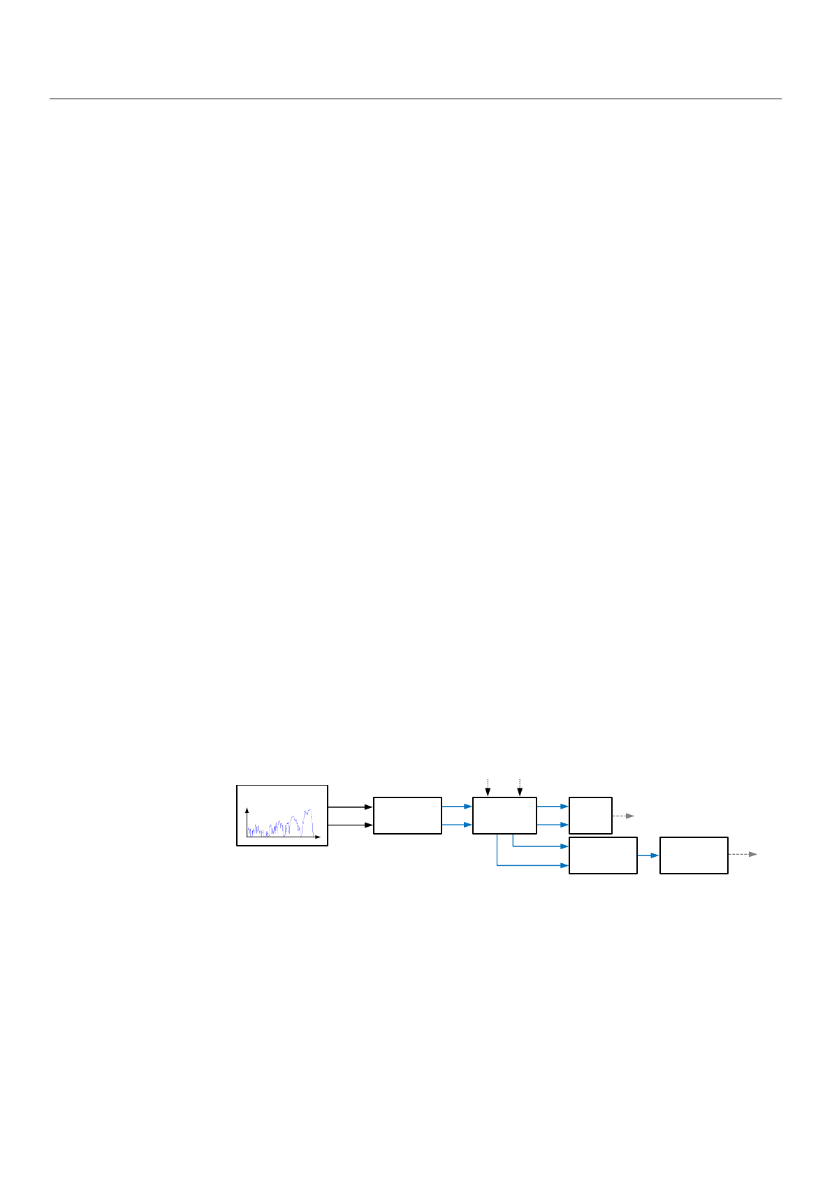
classified into heuristic and optimization-based methods. Figure 2 shows an overview of
the commonly applied methods.
Heuristic operating strategies are implemented as simple rules, maps [12–14], state
machines, or fuzzy controllers [15–17], where the parametrization is frequently carried
out based on the experience of the powertrain’s developers and adjusted by means of
empirical studies and test driving. It often aspires to reduce fuel consumption by shifting
all operating points of the vehicle to an efficient operating area of the ICE. Since the op-
eration of the electric motor is not taken into account optimally, optimal operation in
terms of minimal fuel consumption is not possible. A further approach for parametriza-
CVT
PAR
EM
Mode
T
DHT
Final
Drive
2ST
PG
Internal
Combustion
Engine
(ICE)
Battery Electric Drive
0
i
1/2
i
ED
i
C
1
C
2
C
1
C
2
Figure 1. Basic concept of a hybrid electric powertrain with a DHT.
The operation of the hybrid electric powertrain requires an appropriate operating
strategy, which determines the operation mode of the DHT and the torque distribution
between the ICE and electric motor with the aim of maximal fuel economy. According
to [
9
–
11
], numerous approaches for implementing such strategies are already known and
classified into heuristic and optimization-based methods. Figure 2shows an overview of
the commonly applied methods.
Appl. Sci. 2022, 12, x FOR PEER REVIEW 3 of 18
tion is to incorporate the results from an optimization-based method, which is performed
using representative driving cycles [18–20] (see dotted arrow in Figure 2).
Figure 2. Classification of operation strategies for hybrid electric vehicles.
Usually, heuristic methods provide only suboptimal results, since the parametriza-
tion is based on predefined assumptions without considering real driving behavior. Due
to this disadvantage, it is generally not possible to obtain the minimal possible fuel con-
sumption. However, the main advantage is the simplicity of the method’s implementa-
tion, which makes it suitable for real-time application on a vehicle’s electronic control
units. Moreover, no information on future driving behavior must be known in advance in
order to operate the vehicle.
Optimization-based methods provide optimal results in terms of fuel economy.
Here, fuel consumption is defined to be a cost function, which is minimized for a given
driving cycle by using a mathematical optimization. In general, these methods require a
powertrain model in order to describe the fuel consumption, depending on the vehicle’s
operating point. For this purpose, map-based models are frequently used, where the fuel
consumption of the ICE and the energy efficiency of the electric drive are considered by
means of corresponding maps. When using map-based powertrain models, only numer-
ical optimization methods can be applied. Typical numerical methods for optimiza-
tion-based operating strategies proposed in the literature are Dynamic Programming
(DP) [21,22], Stochastic Dynamic Programming (SDP) [23], Pontryagin’s Maximum Prin-
ciple (PMP) [24,25], Particle Swarm Optimization (PSO) [26], and Sequential Quadratic
Programming (SQP) [27]. Another approach is to use an analytic powertrain model,
where the maps are approximated by convex functions [28]. These functions are often
simple polynomials and enable solving the optimization problem of the operating strat-
egy analytically by means of PMP [29–31]. However, the application is restricted to con-
tinuous control variables (e.g., the torque distribution between ICE and the electric
drive). In [32], the analytical optimization with PMP was combined with DP in order to
consider the gear-shifting command as a discrete control variable. For the same power-
train configuration and control problem, in [33], a combination of DP and an optimiza-
tion based on interior point methods using the SeDuMi tool was applied on a convex
powertrain model.
The advantage of an operating strategy based on mathematical optimization is that
it provides minimal fuel consumption. However, a driving cycle must be known in ad-
vance, and some of the methods require high computational effort. Therefore, these
methods are inapplicable for real vehicle operation but are appropriate for powertrain
analyses and optimizations.
For real driving operation, real-time capable operating strategies are required. An
overview of various methods can be found in [34,35]. Optimization-based methods are
preferred in general, since they consider information about the future driving behavior
and consequently provide better results than heuristic methods. Since the exact driving
behavior is unknown, and due to unforeseeable driving styles and traffic situations,
•Rules
•Maps
•State-Machines
•Fuzzy-Controller
Analytic Numeric
Parametrization
•PMP
Combined
•DP-PMP
•DP-SeDuMi
Heuristic
Methods
Optimization-Based
Methods
Operating Strategies
•DP, SDP
•PMP
•PSO, SQP
Figure 2. Classification of operation strategies for hybrid electric vehicles.

Appl. Sci. 2022,12, 2905 3 of 17
Heuristic operating strategies are implemented as simple rules, maps [
12
–
14
], state
machines, or fuzzy controllers [
15
–
17
], where the parametrization is frequently carried out
based on the experience of the powertrain’s developers and adjusted by means of empirical
studies and test driving. It often aspires to reduce fuel consumption by shifting all operating
points of the vehicle to an efficient operating area of the ICE. Since the operation of the
electric motor is not taken into account optimally, optimal operation in terms of minimal
fuel consumption is not possible. A further approach for parametrization is to incorporate
the results from an optimization-based method, which is performed using representative
driving cycles [18–20] (see dotted arrow in Figure 2).
Usually, heuristic methods provide only suboptimal results, since the parametrization
is based on predefined assumptions without considering real driving behavior. Due to this
disadvantage, it is generally not possible to obtain the minimal possible fuel consumption.
However, the main advantage is the simplicity of the method’s implementation, which
makes it suitable for real-time application on a vehicle’s electronic control units. Moreover,
no information on future driving behavior must be known in advance in order to operate
the vehicle.
Optimization-based methods provide optimal results in terms of fuel economy. Here,
fuel consumption is defined to be a cost function, which is minimized for a given driving
cycle by using a mathematical optimization. In general, these methods require a powertrain
model in order to describe the fuel consumption, depending on the vehicle’s operating point.
For this purpose, map-based models are frequently used, where the fuel consumption of the
ICE and the energy efficiency of the electric drive are considered by means of corresponding
maps. When using map-based powertrain models, only numerical optimization methods
can be applied. Typical numerical methods for optimization-based operating strategies
proposed in the literature are Dynamic Programming (DP) [
21
,
22
], Stochastic Dynamic
Programming (SDP) [
23
], Pontryagin’s Maximum Principle (PMP) [
24
,
25
], Particle Swarm
Optimization (PSO) [
26
], and Sequential Quadratic Programming (SQP) [
27
]. Another
approach is to use an analytic powertrain model, where the maps are approximated by
convex functions [
28
]. These functions are often simple polynomials and enable solving
the optimization problem of the operating strategy analytically by means of PMP [
29
–
31
].
However, the application is restricted to continuous control variables (e.g., the torque
distribution between ICE and the electric drive). In [
32
], the analytical optimization with
PMP was combined with DP in order to consider the gear-shifting command as a discrete
control variable. For the same powertrain configuration and control problem, in [
33
], a
combination of DP and an optimization based on interior point methods using the SeDuMi
tool was applied on a convex powertrain model.
The advantage of an operating strategy based on mathematical optimization is that it
provides minimal fuel consumption. However, a driving cycle must be known in advance,
and some of the methods require high computational effort. Therefore, these methods
are inapplicable for real vehicle operation but are appropriate for powertrain analyses
and optimizations.
For real driving operation, real-time capable operating strategies are required. An
overview of various methods can be found in [
34
,
35
]. Optimization-based methods are
preferred in general, since they consider information about the future driving behavior
and consequently provide better results than heuristic methods. Since the exact driving
behavior is unknown, and due to unforeseeable driving styles and traffic situations, pre-
dictions are used (e.g., based on telemetry data). Well-known real-time capable operating
strategies are the Equivalent Consumption Minimization Strategy (ECMS) [
35
–
37
] and
various Model Predictive Control (MPC) approaches [
38
–
40
], while the optimization-based
implementation of the ECMS is equivalent to PMP [41].
In this contribution, different implementations of the optimization-based EMCS al-
gorithm are analyzed in terms of the theoretically achievable fuel economy. These imple-
mentations are based on different approaches for predicting the future driving cycle, while
the accuracy of the predictions increases with the prediction effort and the quality of the
Appl. Sci. 2022,12, 2905 4 of 17
predicted information. For the analysis, the hybrid electric powertrain given by the basic
concept shown in Figure 1is used. All implementations of the ECMS are evaluated by
means of corresponding powertrain simulations, which are carried out with representative
real-world driving data as the input.
Therefore, in Section 2, the powertrain model used for implementing and evaluating
the optimization-based ECMS is presented. The control of the hybrid electric powertrain by
means of the ECMS requires the definition of an optimization problem and a method for its
solution. Both are described based on the previously defined powertrain model in Section 3
and are applied in Section 4, comprising the ECMS algorithm and the different prediction
methods. Finally, in Section 5, the results of the powertrain simulations considering various
ECMS implementations are evaluated and discussed.
2. Powertrain Model
The ECMS implementation is based on a powertrain model, which is used to perform
a local optimization in order to determine the powertrain’s control signals. Since the
optimization needs to be applied in real time, a powertrain model with low computational
effort and yet a sufficient level of detail is required. This is obtained by the so-called
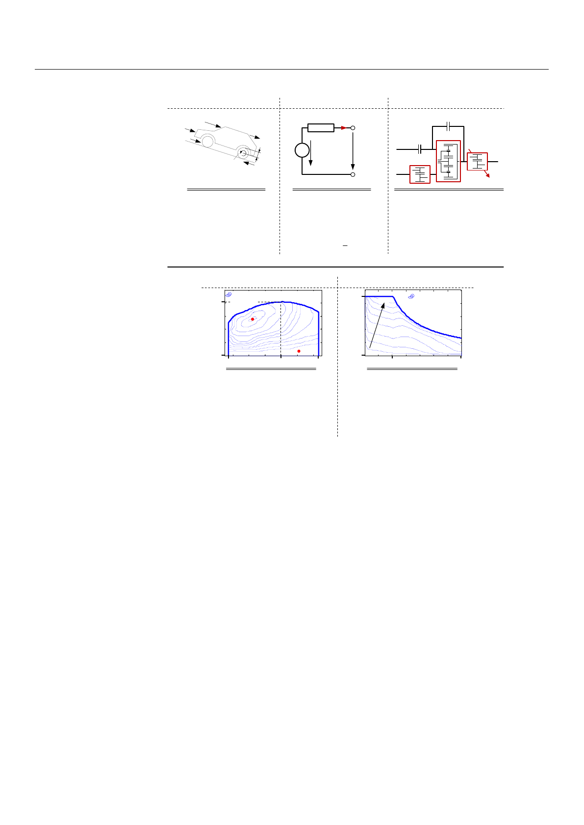
backward approach [
42
]. Starting with the requested acceleration
aveh
and speed
vveh
of
the vehicle, the operating states of each powertrain component are determined backwards
(see Figure 3). A vehicle dynamics model determines the required torque
TFD
and angular
velocity
ωFD
at the final drive. In order to satisfy these requirements, the DHT model
determines the corresponding torques and angular velocities of the ICE and electric drive
considering the transmission’s control variables
sm
and
uED
. It is always assumed that
the ICE and the electric drive are capable of generating the required torque and satisfying
the requested vehicle acceleration, respectively. The submodels of the DHT, ICE, electric
drive, and battery consider stationary states only, as no controllers are required to operate
these components. Only the operation mode of the powertrain must be controlled via
the DHT. Therefore,
sm
defines the mode (CVT, PAR, or EM mode) and
uED
the torque
or angular velocity of the electric drive, definable due to the resulting degree of freedom
in the PAR and CVT modes, respectively. Both control variables are determined by the
ECMS and are considered here as inputs of the powertrain model. Since no dynamic
behavior is considered, the operation mode changes immediately without any transition
(e.g., continuously changing the state of a clutch from engaged to disengaged). The output
of the powertrain simulation is the mass flow rate of the fuel
.
mf
and the state of charge of
the battery SoC.
Appl. Sci. 2022, 12, x FOR PEER REVIEW 4 of 18
predictions are used (e.g., based on telemetry data). Well-known real-time capable oper-
ating strategies are the Equivalent Consumption Minimization Strategy (ECMS) [35–37]
and various Model Predictive Control (MPC) approaches [38–40], while the optimiza-
tion-based implementation of the ECMS is equivalent to PMP [41].
In this contribution, different implementations of the optimization-based EMCS al-
gorithm are analyzed in terms of the theoretically achievable fuel economy. These im-
plementations are based on different approaches for predicting the future driving cycle,
while the accuracy of the predictions increases with the prediction effort and the quality
of the predicted information. For the analysis, the hybrid electric powertrain given by the
basic concept shown in Figure 1 is used. All implementations of the ECMS are evaluated
by means of corresponding powertrain simulations, which are carried out with repre-
sentative real-world driving data as the input.
Therefore, in Section 2, the powertrain model used for implementing and evaluating
the optimization-based ECMS is presented. The control of the hybrid electric powertrain
by means of the ECMS requires the definition of an optimization problem and a method
for its solution. Both are described based on the previously defined powertrain model in
Section 3 and are applied in Section 4, comprising the ECMS algorithm and the different
prediction methods. Finally, in Section 5, the results of the powertrain simulations con-
sidering various ECMS implementations are evaluated and discussed.
2. Powertrain Model
The ECMS implementation is based on a powertrain model, which is used to per-
form a local optimization in order to determine the powertrain’s control signals. Since the
optimization needs to be applied in real time, a powertrain model with low computa-
tional effort and yet a sufficient level of detail is required. This is obtained by the
so-called backward approach [42]. Starting with the requested acceleration veh
a and
speed veh
v of the vehicle, the operating states of each powertrain component are deter-
mined backwards (see Figure 3). A vehicle dynamics model determines the required
torque FD
T and angular velocity FD
ω
at the final drive. In order to satisfy these re-
quirements, the DHT model determines the corresponding torques and angular veloci-
ties of the ICE and electric drive considering the transmission’s control variables m
s
and
ED
u. It is always assumed that the ICE and the electric drive are capable of generating the
required torque and satisfying the requested vehicle acceleration, respectively. The
submodels of the DHT, ICE, electric drive, and battery consider stationary states only, as
no controllers are required to operate these components. Only the operation mode of the
powertrain must be controlled via the DHT. Therefore, m
s
defines the mode (CVT, PAR,
or EM mode) and ED
u the torque or angular velocity of the electric drive, definable due
to the resulting degree of freedom in the PAR and CVT modes, respectively. Both control
variables are determined by the ECMS and are considered here as inputs of the power-
train model. Since no dynamic behavior is considered, the operation mode changes im-
mediately without any transition (e.g., continuously changing the state of a clutch from
engaged to disengaged). The output of the powertrain simulation is the mass flow rate of
the fuel f
m
and the state of charge of the battery SoC .
Figure 3. Powertrain model according to the backward approach and the basic concept shown in
Figure 1.
ICE
Driving Cycle
v
t
Electric
Drive
DHT
Battery
Vehicle
Dynamics
veh
v
veh
a
FD
T
FD
ω
ICE
T
ICE
ω
ED
TSoC
ED
ω
el
P
f
m
m
s
ED
u
Figure 3.
Powertrain model according to the backward approach and the basic concept shown in
Figure 1.
Figure 4shows the submodels of the powertrain and their most significant parameters.
The models of the ICE and electric drive are map-based, whereby only the state behavior of
the components is considered. To determine the specific fuel consumption
be
and power
loss PED,loss, the corresponding torques and speeds are used.
Appl. Sci. 2022,12, 2905 5 of 17
Appl. Sci. 2022, 12, x FOR PEER REVIEW 5 of 18
Figure 4 shows the submodels of the powertrain and their most significant param-
eters. The models of the ICE and electric drive are map-based, whereby only the state
behavior of the components is considered. To determine the specific fuel consumption e
b
and power loss ED,loss
P, the corresponding torques and speeds are used.
Figure 4. Models of the powertrain components and the most important parameters.
The vehicle dynamics are considered in a longitudinal direction only. The torque
FD
T and angular velocity FD
ω
at the final drive are determined according to the fol-
lowing equation:
()
()
FD w drag veh roll downhill veh veh ,TrFv FF ma=⋅ + + + ⋅ (1)
with the radius of the wheels w
r, the vehicle mass veh
m, the vehicle speed veh
v, and the
vehicle acceleration veh
a (extracted from the driving cycle). The forces represent the
driving resistances comprising the drag force drag
F, the rolling friction force roll
F
, and the
downhill force downhill
F. In order to consider the inertias of the wheels and the flywheel
mass of the ICE, equivalent masses are added to the overall vehicle mass. In the case of the
flywheel mass, the average transmission ratio is used for parameter conversion.
By means of the torque FD
T and the rotational speed FD
ω
at the final drive, the
model of the DHT is evaluated (i.e., the torques and rotational speeds of the ICE and the
electric drive are determined by considering the operation mode):
BatteryVehicle Dynamics
x,drag veh veh,x
(,, )FfAcdv=
0
x
F=
veh
m
x
veh veh,x
ma⋅
x,roll
F
x,downhill
F
r
f
mg=⋅⋅ w
r
FD
T
DHT
2
C
ICE
T
ICE
ω
ED
T
ED
ω
1
C0
i
ED
i
1/2
i
FD
T
FD
ω
Vehicle mass
Projected
frontal area
Drag coefficient
Rolling friction
coefficient
veh 1920kgm=
2
veh 2.6mA=
r0.01f=
w0.25c=
Internal cell
voltage
Battery
capacity
Number of
cells
Internal cell
resistance
0,nom 3.75VV=
cell,nom 40AhQ=
i 2.6mΩR=
cell 80z=
Stationary gear
ratio plan. gear
Gear ratio for
electric motor
Gear ratio
first gear
Gear ratio
second gear
02.2i=
ED 1.9i=
23.39i=
16.79i=
V
number of cells
i ()
R
SoC
Batt
i
cell
V
0()VSoC
cell
z
Electric Drive
ICE
min.
spec. fuel consumption b
e
in
g/kWh
ICE,max
T
ICE,max
n
ICE,min
nICE,1
n
0
min
max power losses
P
ED,loss
in W
ED,max
T
ED,max
n
ED,1
n
0
Maximal
torque
Rotational
speed @
Minimal rota-
tional speed
Maximal rota-
tional speed
ICE,max 190 NmT=
1
ICE,1
-
4100minn=
-1
ICE,min 6400minn=
-1
ICE,min 800minn=
ICE,max
T
Maximal
torque
Rotational speed
@ max. power
Maximal rota-
tional speed
ED,max 210NmT=
1
ED,1
-
5700minn=
-1
ED,max 15,000minn=
Figure 4. Models of the powertrain components and the most important parameters.
The vehicle dynamics are considered in a longitudinal direction only. The torque
TFD
and angular velocity
ωFD
at the final drive are determined according to the following
equation:
TFD =rw·Fdrag(vveh)+Froll +Fdownhill +mveh·aveh, (1)
with the radius of the wheels
rw
, the vehicle mass
mveh
, the vehicle speed
vveh
, and the
vehicle acceleration
aveh
(extracted from the driving cycle). The forces represent the driving
resistances comprising the drag force
Fdrag
, the rolling friction force
Froll
, and the downhill
force
Fdownhill
. In order to consider the inertias of the wheels and the flywheel mass of the
ICE, equivalent masses are added to the overall vehicle mass. In the case of the flywheel
mass, the average transmission ratio is used for parameter conversion.
By means of the torque
TFD
and the rotational speed
ωFD
at the final drive, the model
of the DHT is evaluated (i.e., the torques and rotational speeds of the ICE and the electric
drive are determined by considering the operation mode):
sm=
jfor CVT-Mode in j-th gear,
j+2 for PAR-Mode in j-th gear,
j+4 for EM-Mode in j-th gear,
(2)
where
j
denotes the gear in which the corresponding mode is driven. Since a two-speed
transmission is considered, each operation mode can be driven in two speeds
(j∈{1, 2})
.
Loading more pages...