
4804 | Soft Matter, 2021, 17, 4804–4817 This journal is © The Royal Society of Chemistry 2021
Cite this: Soft Matter, 2021,
17, 4804
A pair of particles in inertial microfluidics: effect
of shape, softness, and position†
Kuntal Patel * and Holger Stark
Lab-on-a-chip devices based on inertial microfluidics have emerged as a promising technique to
manipulate particles in a precise way. Inertial microfluidics exploits internal hydrodynamic forces and the
mechanical structure of particles to achieve separation and focusing. The article focuses on the
hydrodynamic interaction of two particles. This will help to develop an understanding of the dynamics of
particle trains in inertial microfluidics, which are typical structures in multi-particle systems. We perform
three-dimensional lattice Boltzmann simulations combined with the immersed boundary method to
unravel the dynamics of various mono- and bi-dispersed pairs in inertial microfluidics. We study the
influence of different starting positions for mono- and bi-dispersed pairs. We also change their
deformability from relatively soft to rigid and choose spherical and biconcave particle shapes. The
observed two-particle motions in the present work can be categorized into four types: stable pair, stable
pair with damped oscillations, stable pair with bounded oscillations, and unstable pair. We show that
stable pairs become unstable when increasing the particle stiffness. Furthermore, a pair with both
capsules in the same channel half is more prone to become unstable than a pair with capsules in
opposite channel halves.
1 Introduction
Biomedical studies of biological cells play a crucial role in
diagnosing several fatal diseases
1
such as malaria,
2
cancer,
3,4
and the human immunodeficiency virus (HIV) infection,
5
to
name a few. In recent years, microfluidic
6
lab-on-a-chip
devices
7
have emerged as a promising technique to precisely
manipulate and control biological cells needed on a
commercial level.
8
Lab-on-a-chip devices for separating particles
and biological cells rely on external force fields or internal
hydrodynamic forces.
9
Lab-on-a-chip techniques using external
force fields include optical tweezers,
10
dielectrophoresis,
11
magnetophoresis,
12
and acoustophoresis.
13
On the other hand,
deterministic lateral displacements at low Reynolds number using
appropriately placed pillars
14
and inertial microfluidics
15–20
exploit internal hydrodynamic forces to achieve particle
separation. In contrast to common microfluidic lab-on-a-chip
devices in which fluid inertia is negligible, inertial microfluidics
operates in an intermediate range between Stokes and turbulent
regimes, where flow is still laminar. The possibility to attain high
throughput makes inertial microfluidics an attractive option
among other microfluidic particle-separation techniques. In this
article, we investigate how different factors such as shape, softness,
and position influence the motion of a pair of particles in a
microfluidic channel.
Inertial focussing was first reported by Segre
´and Silberberg
for solid particles with the well-known tubular pinch effect
21,22
and
then spurred numerous theoretical,
23–26
computational,
19,27–30
and
experimental
31–34
studies to gain a deeper understanding of
this phenomenon. Inertial migration of a neutrally buoyant
solid particle is essentially the result of a balance between
shear-gradient lift force, directed towards the channel wall,
35
and a wall repulsion force, directed towards the channel
center.
36
Applying an external force to the solid particle along
the channel axis, the resulting Saffman force
37
also contributes
significantly to the force balance in the cross-stream direction.
For almost five decades from the observation of the Segre
´–
Silberberg effect, inertial migration was mainly a blue-skies-
research problem. In 2007 Di Carlo et al.
38
demonstrated
ordering and separation of particles in a microchannel using
inertial focussing, which gave rise to the field of inertial
microfluidics. Subsequently, Hur and co-workers
39
experimentally
showed inertia-driven separation and enrichment of deformable
capsules. Soft capsules experience an additional lift force induced
by the deformability of the cell, which drives them towards
the channel center and which therebycompeteswiththeinertial
lift force.
40
For biomedical applications of inertial microfluidics it is
crucial to strive for a deeper understanding of the inertial
Institut fu
¨r Theoretische Physik, Technische Universita
¨t Berlin, Hardenbergstr. 36,
10623 Berlin, Germany. E-mail: kuntal.h.patel@tu-berlin.de
†Electronic supplementary information (ESI) available. See DOI: 10.1039/
d1sm00276g
Received 22nd February 2021,
Accepted 9th April 2021
DOI: 10.1039/d1sm00276g
rsc.li/soft-matter-journal
Soft Matter
PAPER
Open Access Article. Published on 19 April 2021. Downloaded on 11/22/2021 9:52:27 AM.
This article is licensed under a
Creative Commons Attribution 3.0 Unported Licence.
View Article Online
View Journal
| View Issue
This journal is © The Royal Society of Chemistry 2021 Soft Matter, 2021, 17, 4804–4817 | 4805
migration of deformable capsules. The dynamics of soft
capsules is widely studied at low Reynolds numbers in
canonical flows
41–45
and cellular blood flow simulations.
46–49
Only recently, inertial microfluidics of deformable cells has
caught attention.
20,50–58
Using two-dimensional numerical
simulations, Shin and Sung
51
showed that the final equilibrium
position for a given value of capsule elasticity varies with the
Reynolds number. In their following work
54
they identified
different types of capsule dynamics such as tank-treading,
swinging, and tumbling. According to Kilimnik et al.
50
the
steady-state position of a deformable capsule in the lateral
direction is independent of the flow rate and it only
depends on the softness. This was later verified by Schaaf and
Stark
20
using 3D lattice Boltzmann simulations. They also
proposed that the inertial lift force in the vicinity of the
channel center scales as a cube of capsule radius. More
recently, Alghalibi and colleagues
58
investigated cross-stream
inertial migration of a soft particle in pipe flow. Interestingly,
they found that irrespective of the particle’s softness and
the flow rate, the particle always ends up at the channel
center for an initial particle diameter of 0.2 times the pipe
diameter.
Practical applications require manipulation of several soft
particles at a time and, hence, it is important to study how
particles interact in flow. There are a few systematic studies in
literature to understand the interaction of solid and soft
particles in inertial microfluidics. Yan et al.
59
investigated the
dynamics of two solid particles in linear shear flow generated
by two plates moving against each other. They observed that
particles either settle down on the centerline where flow
velocity is zero or exhibit oscillatory motion when released
from symmetric initial positions. Schaaf et al.
60
reported that
for two closely placed solid particles in a channel flow, the
inertial lift forces acting on the leading and lagging particles
differ significantly. In their subsequent work
61
they extended
the understanding of a particle pair to study the behavior of
particle trains
62
in inertial microfluidics. At low Reynolds
numbers, Lac et al.
63
and Aouane et al.
64
investigated the
interaction of two soft capsules in shear and Poiseuille flows,
respectively. The inertial counterparts of these two problems
were also studied. Doddi and Bagchi
65
observed a transition
from irregular self-diffusion
66
to different types of spiraling
motions (outward, fixed orbit, and inward) with increasing
Reynolds number. Lan and Khismatullin
67
reported that a pair
of deformable cells in a rectangular microchannel undergoes
either swapping or passing trajectories, while deformable cells
in a series experience damped oscillations. Like Lan and
Khismatullin,
67
Schaaf et al.
60
also observed these swapping and
passing trajectories for a pair of solid particles. Kru
¨ger et al.
68
looked into the suspension of deformable capsules in Poiseuille
flow at finite Reynolds numbers. They discovered that particle–
particle interactions enhance the migration towards the channel
center for sufficiently large Reynolds and capillary numbers.
In the present work we perform three-dimensional lattice-
Boltzmann simulations combined with the immersed boundary
method
20,60,69
to investigate the dynamics of mono- and
bi-dispersed particle pairs. They flow through a square micro-
channel in the inertial regime. We systematically investigate the
effect of different starting positions for mono- and bi-dispersed
pairs. We also vary their deformability from relatively soft to
rigid and choose spherical and biconcave particle shapes.
Reynolds number, particle radius, and axial particle distance
are kept the same in all the cases. The observed dynamics of
the different mono- and bi-dispersed particle pairs can be
categorized into four types: stable pair, stable pair with damped
oscillations, stable pair with bounded oscillations, and
unstable pair.
The outline of the article is as follows. In Section 2 we
discuss the computational setup and simulation para-
meters of the problem and explain the lattice Boltzmann
simulations. Results from the numerical investigations are
presented in Section 3 and we close with concluding remarks
in Section 4.
2 Computational setup and
numerical methodology
2.1 Microfluidic setup for a flowing pair of particles
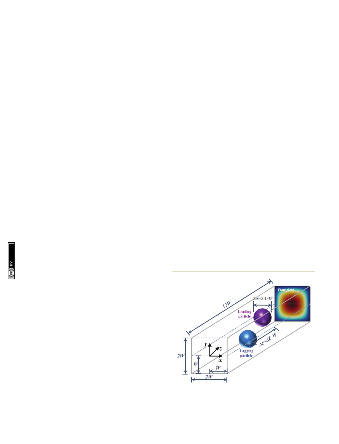
Fig. 1 shows the schematic of our microfluidic setup. We study
the hydrodynamic interaction and inertial migration of a
flowing pair of soft particles in a quadratic microchannel. We
start from a fully-developed Poiseuille flow and place two
particles in the midplane at y= 0. We apply periodic boundary
conditions in the z-direction along the channel axis and the no-
slip boundary condition at the channel walls in the remaining
directions. The length of the microchannel is large enough so
that particles do not interact with their periodic images unless
the axial separation becomes as large as the channel length.
The pressure gradient or force density arequired to pump the
fluid through the channel is calculated from the analytical
Fig. 1 Computational setup for a pair of neutrally buoyant flowing parti-
cles in a microchannel. Two particles of non-dimensional radius aand
initial axial separation Dzare placed in a fully developed Poiseuille flow in
the midplane at y=0.
Paper Soft Matter
Open Access Article. Published on 19 April 2021. Downloaded on 11/22/2021 9:52:27 AM.
This article is licensed under a
Creative Commons Attribution 3.0 Unported Licence.
View Article Online
4806 | Soft Matter, 2021, 17, 4804–4817 This journal is © The Royal Society of Chemistry 2021
expression for the velocity field of a Poiseuille flow:
70
Uzðx;yÞ¼
16W2a
p3ZX
1
n;odd
1
n31
cosh npx
2W
cosh np
2
2
6
43
7
5
sin npðyþWÞ
2W
;
(1)
where U
z
,W, and Zare the axial velocity, channel half-width and
dynamic viscosity of the fluid, respectively.
2.2 Coupled lattice Boltzmann finite element immersed
boundary method (LBFEIBM)
2.2.1 Lattice Boltzmann method. In the last two decades
the lattice Boltzmann method
71,72
has emerged as an efficient
alternative to conventional techniques of computational
fluid dynamics. In particular, it was applied to multiphysics
problems involving soft matter and fluid flow.
73
The lattice
Boltzmann method operates at the mesoscale and provides a
solution of the discretized Boltzmann equation. It is based on
the lattice Boltzmann equation that governs the advection and
collision of populations of particles. They are described by
distribution functions f
i
(x,t) for a discrete set of velocity vectors
c
i
. In time step Dtthese distributions evolve according to
fixþciDt;tþDtðÞfiðx;tÞ¼1
tfeq
iðx;tÞfiðx;tÞ½þFiDt;(2)
where
feq
iðx;tÞ¼wir1þuci
cs2þuci
ðÞ
2
2cs4uu
2cs2
!
(3)
stands for the local equilibrium distribution of velocity vectors c
i
relative to flow velocity u. Here, we implement the D3Q19 lattice
with 19 discrete velocity vectors chosen from c
i
={(0,0,0),cyc(1,
0, 0), cyc(1, 1, 0)} with weights w
i
= {1/3, 1/18, 1/36}.
Furthermore, c
s
in eqn (3) is the speed of sound and the relaxation
time tin eqn (2) is related to the kinematic viscosity n¼
cs2Dtt1
2
,wherecs2¼1
3in lattice units. The last term in eqn (2)
is due to the forcing scheme proposed by Guo et al.
74
It takes into
account the force density driving the fluid and forces exerted by
particles. Based on this scheme, a body force density fis related to F
i
as
Fi¼wi11
2t
ciu
cs2þciu
cs4ci
f:(4)
In order to obtain the macroscopic picture of the flow field, fluid
density rand momentum density ruat each lattice node can be
calculated using the zeroth and first moments of the populations f
i
:
r¼X
i
fi;(5)
ru¼X
i
cifiþDt
2f:(6)
We enforce the no-slip condition at channel walls using the
regularized method of Latt and Chopard.
75,76
The numerical
accuracy of our simulations is maintained by setting the
relaxation time tr1. Please refer to ref. 20 for further details.
The numerical solution of the lattice Boltzmann equation is
obtained using an open-source parallel lattice Boltzmann
solver from the Palabos project,
77
while implementation of
the immersed boundary method and particle dynamics uses
in-house libraries.
2.2.2 Modeling of soft capsules. We employ the finite
element method to discretize the surface of the particle with P1
elements,
78
i.e., linear triangular elements. Tessellation of the
particle surface is achieved by dividing each triangle of an
icosahedron into four triangles (for more details refer to ref. 69)
and the newly created nodes are then radially shifted to the
circumsphere. The process is repeated until the distance
between two neighboring nodes approaches the lattice spacing.
This procedure of generating mesh from a highly symmetric
solid (icosahedron in the present case) enables us to achieve
superior mesh quality in terms of isotropy and homogeneity.
69
The same procedure is used for the solid particles as well.
The capsule dynamics is determined by a combination
of strain, bending, and volume energies. For the strain energy
we rely on the Skalak model
79
valid for an isotropic and
homogeneous capsule. It is formulated as a function of the
strain invariants of the Green strain tensor and given as
Es¼Iks
12 I12þ2I12I2
þka
12I22
dA;(7)
where k
s
is the shear modulus and k
a
is the area dilation
modulus. The strain invariants I
1
and I
2
can be expressed in
terms of in-plane principal extension ratios l
1
and l
2
:
I
1
=l
12
+l
22
2, (8)
I
2
=l
12
l
22
1. (9)
The discretized version of the bending energy proposed by
Helfrich
80,81
takes the form
Eb¼ffiffiffi
3
pkbX
ij
hi
1cos yij y0
ij
hi
;(10)
where k
b
is the bending modulus, y
ij
is the angle between the
area normal vectors of two neighboring surface elements, and
y
0
ij
is the reference angle from the undeformed (initial) state.
Implementation of the bending energy prevents cusp formation
and buckling of soft capsules.
In this work, we consider soft particles with an impermeable
membrane. To implement the constraint of constant volume, at
least approximately, we choose a standard method and incor-
porate the volume energy
82
Ev¼kv
2
VV0
2
V0;(11)
where k
v
,Vand V
0
are the volume modulus, actual capsule
volume, and reference volume, respectively. To keep the volume
changes below 1%, we choose k
v
= 75 000rn
2
/W
2
. Note, these
changes do not affect the dynamics of the particle.
Soft Matter Paper
Open Access Article. Published on 19 April 2021. Downloaded on 11/22/2021 9:52:27 AM.
This article is licensed under a
Creative Commons Attribution 3.0 Unported Licence.
View Article Online

This journal is © The Royal Society of Chemistry 2021 Soft Matter, 2021, 17, 4804–4817 | 4807
Following Kru
¨ger et al.
68
and Schaaf and Stark,
20
we set
k
a
/k
s
= 2 and k
b
/(k
s
a
2
) = 2.87 10
3
. We can compare our
parameters with the ones for red blood cells. To mimic their
the mechanical behavior in blood flow simulations, the ratio
k
b
/(k
s
a
2
) is set to 2.36 10
3
,
47
which is very close to the value
in present simulations. However, the ratio k
a
/k
s
in current
simulations is significantly smaller than that used for a healthy
red blood cell, which allows our spherical capsules to deform
significantly.
The total force acting on node ican be obtained from the
principle of virtual work;
83
given as F
i
=q[E
s
+E
b
+E
v
]/qx
i
.
The derivatives of strain, bending, and volume energies were
derived analytically and then inserted directly into the solver to
save computational costs. The analytical form of the derivatives
can be found in ref. 84.
2.2.3 Modeling of solid particles. The motion of a neutrally
buoyant solid particle is governed by Newton’s law and its
equivalent for the angular momentum:
S(t+Dt)=S(t)+U(t), (12)
MU(t+Dt)=MU(t)+F
fluid
+F
Feng
, (13)
Ix(t+Dt)=Ix(t)+T
fluid
+T
Feng
, (14)
where, S,M,I,U, and xare the particle position, mass, moment
of inertia, linear velocity, and angular velocity, respectively.
Force F
fluid
and torque T
fluid
exerted by the fluid on the particle
are computed using the iterative procedure of Inamuro,
85
which ensures the no-slip condition at the boundary of the
solid particle. Suzuki and Inamuro
86
demonstrated that for
simulating the dynamics of solid particles at finite Reynolds
numbers correctly, the effect of a fictitious fluid inside the solid
particle must be taken into account when using the immersed
boundary method. Therefore, one needs to introduce Feng’s
rigid body approximation
87
with the help of additional forces
and torques, F
Feng
and T
Feng
, respectively.
2.2.4 Immersed boundary method. The hydrodynamics of
soft and solid particles in inertial microfluidics is essentially a
fluid–structure interaction (FSI) problem on the micron scale.
In the present case, the motion of the bulk fluid in a micro-
channel is responsible for the movement of particles; in turn,
particles exert forces on the fluid via their surfaces. We imple-
ment this interaction between fluid and particles using the
immersed boundary method (IBM) of Peskin.
88,89
The
immersed boundary method is one of the fluid–structure
interaction methods that belong to the mixed Eulerian-
Lagrangian framework. There also exist fully Eulerian and
Lagrangian FSI methods (see Fig. 1 of ref. 90 for more details).
The classical IBM treats vertices of the P
1
elements of the
discretized particle surfaces as Lagrangian markers. The
advection velocity :
x
i
of Lagrangian markers is obtained using
an interpolation of the velocity values ufrom neighboring
Eulerian points, which in our case are the lattice nodes of the
lattice Boltzmann method:
_
xiðtþDtÞ¼X
X
uðX;tþDtÞdðXxiðtÞÞ;(15)
In contrast, the body force density f
˜exerted by Lagrangian
markers on neighboring Eulerian points is computed using the
spreading operation:
~
fðX;tÞ¼X
i
FiðtÞdðXxiðtÞÞ:(16)
Following ref. 88 the discretized delta function d(Xx
i
(t)) in
eqn (15) and (16) are represented as d(Xx
i
(t)) = f(Xx
i
(t))f(Y
y
i
(t))f(Zz
i
(t)), where
jðrÞ¼
1
832jrjþ ffiffiffiffiffiffiffiffiffiffiffiffiffiffiffiffiffiffiffiffiffiffiffiffiffiffiffiffi
1þ4jrj4r2
p
0jrj1
1
852jrj ffiffiffiffiffiffiffiffiffiffiffiffiffiffiffiffiffiffiffiffiffiffiffiffiffiffiffiffiffiffiffiffiffiffi
7þ12jrj4r2
p
1jrj2
02jrj:
8
>
>
>
>
>
>
<
>
>
>
>
>
>
:
(17)
The interaction between soft capsules and the bulk fluid
is resolved using the classical IBM. However, for solid particles
we employ interpolation and spreading operations in an
iterative manner
85,86
to obtain the force F
fluid
and torque T
fluid
directly from the flow field. Then, advection velocity Uis
obtained using eqn (13). This particular approach is known
as the multi-direct-forcing variation of the immersed boundary
method.
91,92
2.3 Simulation parameters
In our microfluidic setup we simulate two types of particle
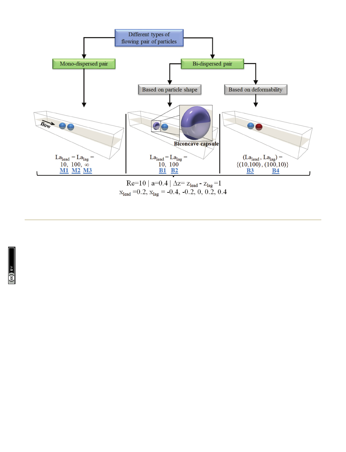
pairs, mono- and bi-dispersed (see Fig. 2). Mono-dispersed
pairs consist of spherical particles of the same stiffness.
Bi-dispersed pairs are classified into two subtypes; first, a pair
with particles of different shapes but the same stiffness, and
second, a pair with particles of varying stiffness but the same
shape. We consider the combination of a spherical (leading)
and biconcave (lagging) particle for the first type, and for the
second type, two spherical particles. The initial orientation of a
biconcave particle in the flow field is shown in a magnified view
in Fig. 2. We apply the transformation
xbicon:¼1:2xsphere;
ybicon:¼1:2ysphere;
(18)
zbicon:¼0:60:207 þ2xsphere2þysphere2
a2
1:123 xsphere2þysphere2
a2
2#zsphere;
to the vertices of a spherical particle of radius ato model the
biconcave shape.
93,94
Inallthecaseswesetthenon-dimensionalparticleradiusa
and the initial axial separation Dzequal to 0.4 and 1, respectively.
For the biconcave particle the radius characterizes the spherical
particle from which it is generated using eqn (18). The value of
the Reynolds number Re = 2WU
max
/nis fixed to 10 in all the
simulations. Here, U
max
is the maximum fluid velocity in the
channel center and nis the kinematic viscosity. Note, in a
typical inertial microfluidics setup, the Reynolds number varies
Paper Soft Matter
Open Access Article. Published on 19 April 2021. Downloaded on 11/22/2021 9:52:27 AM.
This article is licensed under a
Creative Commons Attribution 3.0 Unported Licence.
View Article Online
4808 | Soft Matter, 2021, 17, 4804–4817 This journal is © The Royal Society of Chemistry 2021
from 1 to 100
17
. Following Schaaf and Stark,
20
we use the
Laplace number to define the softness of the particle; it is
given as
La = k
s
a/rn
2
. (19)
In our simulations we consider cases with relatively soft
(La = 10) and stiff (La = 100) particles (please refer to Fig. 2).
We also include a mono-dispersed pair of solid particles (case
with La = Nin Fig. 2) to compare the dynamics of soft and solid
particles of spherical shape. For comparison we note that for a
red blood cell suspended in plasma, one has a=410
6
m and
k
s
= 5.3 10
6
Nm
1
,
47
and the Laplace number turns out to
be 0.0212.
In practice, there might exist a viscosity contrast between the
fluid within soft particles (cytoplasm in biological cells) and the
bulk liquid (Z
cyto
/Z
bulk
41). For example, the cytoplasmic
viscosity of the red blood cell is five times the plasma viscosity
Z
plasma
= 1 mPa s.
47
Moreover, tumour cells such as A549 can
have cytoplasmic viscosity in the range of 144.8 to 1390.7 Pa s,
95
which is several orders of magnitude higher than the plasma
viscosity. We shortly summarize what influence this will have.
An increase in the viscosity of the interior fluid or cytoplasm
attenuates the deformation of soft particles and biological
cells.
50
Thus, while for a very soft particle a viscosity contrast
close to one should not significantly alter the migration
dynamics, a viscosity contrast significantly larger than one
makes particles less deformable and modifies their equilibrium
positions. In the case of relatively stiff particles, the viscosity
contrast will have a negligible influence on the particle
dynamics. Moreover, for biconcave soft particles in inertial
flows with Re BO(1), there exists a critical value of viscosity
contrast above which the transition from tank-treading to
tumbling motion takes place.
52
Later, we will see that biconcave
particles in the present work already exhibit tumbling motion.
With this in mind, we set the density and viscosity of the soft
particle identical to the values of the bulk fluid.
In each simulation we fix the leading particle position in the
x-direction to 0.2 and vary the position of the lagging particle
from 0.4 to 0.4 in steps of 0.2. The leading particle’s starting
position is kept sufficiently far from the stable equilibrium
point of isolated particles (see Fig. 5 and 9) so that disturbances
from the lagging particle can have a significant effect on the
motion of the leading particle. The implemented LBFEIBM
solver has been employed in a series of works by our
group
19,20,60,61
(see Appendix A for benchmarking). According
to our previous work we discretize the channel width with
90 lattice nodes for the case of soft particles and 75 lattice
nodes for solid particles. In our simulations, the necessity of a
high grid resolution arises to ensure the proper coupling
between particles and the bulk fluid. Moreover, relatively more
lattice nodes are required in the case of soft particles to capture
the particle deformation and lift force accurately. Lastly, the
surface of soft and solid particles is discretized using 20 480 P1
elements.
Fig. 2 Classification of different types of particle pairs with radius a. Each pair type is simulated for the same initial distance Dz, for different values of
softness La
lead
,La
lag
, and five sets of different initial positions x
lead
,x
lag
. Alphanumeric labels M1–M3 and B1–B4 are the identification tags given to each
case. Note that the mono-dispersed pair with La = Ncorresponds to the case of solid particles.
Soft Matter Paper
Open Access Article. Published on 19 April 2021. Downloaded on 11/22/2021 9:52:27 AM.
This article is licensed under a
Creative Commons Attribution 3.0 Unported Licence.
View Article Online
Loading more pages...