
sensors
Article
A Tangible Solution for Hand Motion Tracking in
Clinical Applications
Christina Salchow-Hömmen *,† , Leonie Callies †, Daniel Laidig, Markus Valtin,
Thomas Schauer and Thomas Seel
Control Systems Group, Technische Universität Berlin, Berlin 10587, Germany;
*Correspondence: salchow@control.tu-berlin.de; Tel.: +49-(0)30-314-24893
† These authors contributed equally to this work.
Received: 21 November 2018; Accepted: 23 December 2018; Published: 8 January 2019
Abstract:
Objective real-time assessment of hand motion is crucial in many clinical applications
including technically-assisted physical rehabilitation of the upper extremity. We propose an
inertial-sensor-based hand motion tracking system and a set of dual-quaternion-based methods for
estimation of finger segment orientations and fingertip positions. The proposed system addresses the
specific requirements of clinical applications in two ways: (1) In contrast to glove-based approaches,
the proposed solution maintains the sense of touch. (2) In contrast to previous work, the proposed
methods avoid the use of complex calibration procedures, which means that they are suitable
for patients with severe motor impairment of the hand. To overcome the limited significance of
validation in lab environments with homogeneous magnetic fields, we validate the proposed system
using functional hand motions in the presence of severe magnetic disturbances as they appear in
realistic clinical settings. We show that standard sensor fusion methods that rely on magnetometer
readings may perform well in perfect laboratory environments but can lead to more than
15 cm
root-mean-square error for the fingertip distances in realistic environments, while our advanced
method yields root-mean-square errors below 2 cm for all performed motions.
Keywords:
inertial sensor; inertial measurement unit; real-time motion tracking; hand tracking;
magnetic disturbances; dual quaternions; hand and finger kinematics; rehabilitation; functional
electrical stimulation
1. Introduction
1.1. Motivation
Assistive technology for the recovery of patients who suffer from motor impairments due to an
injury of the spinal cord (SCI) or due to a stroke is of increasing interest in an aging society. Functional
electrical stimulation (FES) has proven to be a promising tool to help patients regain some mobility of
the paralyzed limbs [
1
]. Many systems proposed in the literature employ an open-loop control of the
neuro-muscular stimulation [
2
]. As the human body and the human hand in particular are complex,
highly nonlinear, and time-variant systems, the same stimulation often leads to entirely different
outcomes in different patients and in different rehabilitation sessions [
3
]. Closed-loop control of FES
has the potential to improve the effectiveness and the usefulness of the therapy significantly. This has
been demonstrated for gait support [
4
,
5
] as well as for upper limb motion support [
6
–
8
]. In the case of
hand motor rehabilitation, a closed-loop approach requires real-time methods for accurate assessment
of hand motion [
9
]. Furthermore, many FES-based systems utilize precise hand motion tracking for
Sensors 2019,19, 208; doi:10.3390/s19010208 www.mdpi.com/journal/sensors

Sensors 2019,19, 208 2 of 27
the identification of optimal stimulation points in electrode arrays on the forearm [
10
,
11
]. Beyond the
feedback control and tuning of hand neuroprostheses, such methods would facilitate, for example,
real-time biofeedback of hand motion and would yield valuable measurement information for robotic
assistive devices [12].
Real-time hand motion tracking is a challenging task due to the large number of finger segments
and degrees of freedom of the joints between them. Moreover, the field of rehabilitation imposes
some specific requirements on the design of a hand motion tracking system. It needs to be portable
to allow the application in various clinical environments or even in the context of supervised home
rehabilitation. Complex calibration procedures must be avoided to make the system suitable for
patients with severe motor impairment of the hand. For the same reason attaching the system to
the hand must be easy and non-restrictive. For example, while gloves may be preferred in gaming
applications, it is not a feasible solution for spastic hands. Furthermore, hygienic aspects have to be
considered, especially if more than one patient uses the system.
Lastly, rehabilitation is typically performed in indoor environments and in the proximity of
electronic devices and objects (e.g., tables, chairs, hand tools) containing ferromagnetic material such
as steel. Therefore, the assumption of a homogeneous magnetic field is not fulfilled in a realistic
rehabilitation setting, which is a problem when it comes to motion tracking with inertial measurement
units (IMU). If an IMU passes by a ferromagnetic object, this induces a short-time magnetic disturbance
that can be detected and treated by adjusting the sensor fusion weight. However, if the hand is
placed near an electronic device or grasps a ferromagnetic object for a long period, the disturbance
does not disappear quickly, and the magnetometer readings are useless during the entire time span.
This severely impedes usability of most existing sensor fusion schemes [
13
,
14
]. A reliable system for
hand motion tracking must measure the fingertip positions despite these challenges.
1.2. Previous Approaches to Hand Motion Tracking
Table 1summarizes and compares available types of measurement systems for hand motion
tracking in clinical applications. Many of the mentioned systems offer a high tracking accuracy
for healthy hands and are optimized for the various applications in virtual and augmented reality.
However, there are unsolved problems when it comes to the use in physical rehabilitation. Optical
systems are subject to line-of-sight restrictions, i.e., they can only track finger segments that are inside
the observation volume of stationarily mounted cameras and are not hidden by other segments or
objects. Moreover, optical systems must either be set up by an expert (in the case of marker-based
systems) or yield only limited accuracy (in the case of marker-free systems) [15].
Instrumented gloves have been proposed with different sensor technologies such as resistive,
optical or inertial sensors [
16
,
17
]. Resistive-bend sensors and optical-fiber sensors are placed in gloves
of varying material to cover the joints of interest [
18
]. This makes them prone to mechanical wear and
it entails the need for a thorough calibration. Moreover, these sensors quantify joint angles and are not
capable of measuring an absolute orientation of the finger segments (cf. Table 1). In contrast, inertial
and magnetic sensors are placed on single finger segments and allow the estimation of velocities and
orientations [
19
], but the calibration and magnetically disturbed environments can hamper practical
application. In general, the usage of gloves has the distinct disadvantage of being difficult to put
onto motor-impaired or even spastic hands of stroke and SCI patients. They must be customized to
individual hand sizes, lead to a reduced sense of touch, and cleaning plus disinfecting is challenging.

Sensors 2019,19, 208 3 of 27
Table 1.
Overview of suggested hand motion tracking systems for clinical applications. This list does
not claim to be complete and rather shows examples. The advantages and disadvantages refer to the
use in closed-loop functional electrical stimulation for grasping.
System Type ExamplesAdvantages and Disadvantages
Optical systems Vicon (Vicon Motion Systems Ltd., (+) accurate
with markers Oxford, UK)
( – ) extensive setup by expert, expensive,
line-of-sight restriction, stationary
Optical systems
Kinect V2 (Microsoft, Redmond, WA,
(+) contactless, affordable
without markers
USA), Leap Motion (Leap Motion,
San Francisco, CA, USA)
( – ) limited accuracy, line-of-sight restriction
Sensor gloves 5DT Data Glove Ultra (5DT Inc., (+) quick setup
with bend sensors
Orlando, FL, USA), Cyperglove III
(CyberGlove Systems Inc. LLC, San
( – ) less sense of touch, glove not suitable for
spastic hand, hygienically problematic,
Jose, CA, USA)
measures only angles (no accelerations/
velocities/positions)
Sensor gloves
IGS Cobra Glove (Synertial, Lewes,
( + ) quick setup, detailed measurements
with IMUs UK), PowerGlove [19,20]
( – ) less sense of touch, glove not suitable for
spastic hand, hygienically problematic, uses
magnetometers and calibration motions
These shortcomings are well reflected in the small number of existing studies that propose systems
for closed-loop FES based on real-time sensing of hand motions. Soska et al. [
2
] introduce a method
to control the joint angles of the affected hand by an iterative learning controller but present only
simulative results without proposing solutions for hand motion tracking. Westerveld et al. [
21
]
used a closed-loop setup in which they selectively activate and control individual finger movements.
They employed a marker-based optical motion capture system to track finger flexion angles as well
as thumb abduction and extension angles. A proportional and a model-predictive controller were
designed and tested in able-bodied volunteers for grasping, holding and releasing two different objects.
Kim et al. [
22
] used a 2D gyroscope on the back of the hand to detect the direction of the hand
motion and a ring-type accelerometer on each finger to measure finger motion. The device is capable
of recognizing simple hand poses and identifying finger-clicking, which means the system can be
used as a wearable computer mouse. It is, however, not capable of estimating the finger segment
orientations and fingertip positions, which are needed to track and quantify the motion of the hand
and its interaction with objects.
Kortier et al. [
19
] further pursue the idea of using gyroscope and accelerometer data for the
tracking of hand motions with a data glove. They apply IMUs consisting of a 3D gyroscope and
a 3D accelerometer to all finger segments and three locations on the back of the hand. In addition,
3D magnetometers are placed at the fingertips and on the back of the hand. Multiple extended Kalman
filters are used to fuse the sensor readings and biomechanical constraints to estimate the orientation
of every sensor. Each measurement is preceded by a calibration protocol that consists of prescribed
poses and precisely defined finger motions, which are used to determine the axes of rotation of all
joints. The authors compare their estimation to an optical system in trials with pinching movements
of thumb and index finger [
19
,
20
]. All results are obtained in a laboratory environment under the
assumption of a perfectly homogeneous magnetic field. Such conditions are rarely found in clinical
practice, and a large number of neurological patients will be unable to perform the required precise
calibration poses and motions properly.
Connolly et al. [
23
] present an IMU-based glove system that aims at measuring finger and
thumb joint movements accurately in patients with rheumatoid arthritis, who are capable of donning
a glove. The system uses inertial sensors connected via stretchable substrate material to calculate joint
angles and angular velocities. The inertial sensor fusion is based on magnetometers, which will yield
false measurements in realistic therapy environments. The motion estimation method requires an

Sensors 2019,19, 208 4 of 27
initial calibration pose. The description of the specific algorithm is very brief, contains no equations,
and indicates that joint angle calculation is based on measured gravitational accelerations, which
implies that the method becomes highly inaccurate if the joint axis is close to vertical. Under laboratory
conditions, the system exhibited root-mean-square errors (RMSE) of
6°
when placed on wooden blocks
cut to specific angles.
Choi et al. [
24
] propose a wireless IMU-based glove system with modular design and a new
orientation estimation algorithm. The algorithm relies on undisturbed magnetometer data and requires
a time-consuming calibration procedure. Their evaluation lacks real-time measurements in realistic
conditions and numeric results with human hands. Recently, Lin et al. [
25
] presented a similar
design. They report a mean error in joint angles under
±3°
for a
15 min
measurement of extension
and flexion. However, they evaluated the system on a customized measurement platform, allowing
only extension and flexion of finger joints, in a laboratory environment under the assumptions of
a perfectly homogeneous magnetic field and with stable sensor biases. It remains unclear how the
system performs on the human hand, where many joints have more than one degree of freedom.
In summary, there exist very few previous contributions that propose solutions for real-time hand
motion tracking. With respect to the requirements of motor rehabilitation in stroke and SCI patients,
further developments are needed. More precisely, a system is required that is easy to put onto spastic
hands, does not rely on magnetometers, is not subject to line-of-sight restrictions, and requires only
a minimum of calibration effort. If such a system can be developed, its accuracy should be evaluated
for functional motions like pinching and grasping objects in a realistic environment with substantial
and permanent magnetic field disturbances.
1.3. The Proposed Approach
In the current contribution, we propose a portable IMU-based sensor system for real-time tracking
of fingertip positions that can, for example, be used in a feedback-controlled hand neuroprosthesis.
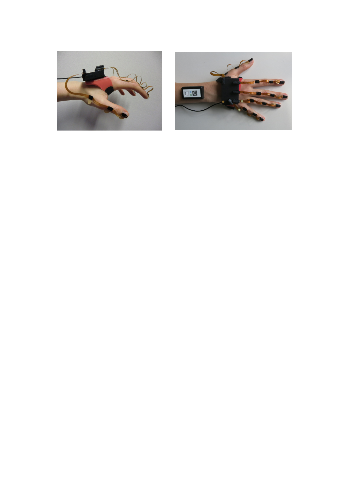
The system is composed of a base unit, which is placed on the back of the hand, and five sensor strips,
which are placed on the segments of the fingers, as depicted in Figure 1. By adhesive attachment,
we avoid the aforementioned disadvantages of gloves. The proposed motion estimation method is
based on the mathematical framework of dual quaternions and aims at avoiding complex calibration
motions and at meeting the requirements of clinical rehabilitation practice. We propose a set of
algorithms using a biomechanical model of the hand that includes all five fingers and captures the 23
main rotational degrees of freedom (DoF) of the hand and finger joints. Besides a method that uses the
full IMU raw data, we also propose a method that refrains from using magnetometer readings to assure
robust motion tracking in the presence of non-ideal magnetic fields. Both methods are compared to
a baseline approach by experimental trials in an optical motion capture lab and in a more realistic
environment with magnetic disturbances. For evaluation and comparison, we focus on the accuracy
of fingertip positions since these are crucial for functional motions of the hand such as pinching or
grasping.
The remainder of the article is organized as follows. We introduce the sensor system and
the necessary biomechanical foundations in Section 2. We continue with an introduction to dual
quaternions and the description of the estimation algorithm. The experimental validation procedure
is described in Section 3. The experimental results are presented in Section 4and are discussed in
Section 5.
Sensors 2019,19, 208 5 of 27
Figure 1.
IMU-based modular hand sensor system for real-time motion tracking of the fingertip
positions. The system consists of a base unit on the hand back, a wireless IMU on the forearm, and up
to five sensor strips, each equipped with three IMUs.
2. Materials and Methods
2.1. Hand Sensor System Hardware
The novel IMU-based hand sensor system shown in Figure 1was recently developed as part of
a feedback-controlled neuroprosthesis [
26
–
28
]. The hardware setup was inspired by Kortier et al. [
19
].
It consists of a mandatory base unit that is placed on the back of the hand, up to five sensor strips
that can be fixed to the fingers, and an optional wireless inertial sensor for the forearm to track the
wrist angles if desired. The system is compact and portable as well as modular in the sense that sensor
strips can be removed and replaced arbitrarily. These characteristics increase the flexibility in different
therapy settings and for multiple hand sizes making the system more practical and easier to maintain.
The base unit is a custom printed circuit board placed in a 3D printed shell (6.1
×
4.0
×
1.1 cm).
It includes a 9D inertial sensor (MPU9259, InvenSense Inc., San Jose, CA, USA; footprint 3
×
3 mm)
and five connectors for the sensor strips. A USB connection to the computer facilitates power supply
and data transfer.
To capture hand motions in high detail, the sensor system measures the translational and rotational
motion of each finger segment and the hand back. Consequently, each sensor strip connects three 9D
inertial sensors (MPU9259) through a
19 cm
long flexible printed circuit board. One sensor is attached
to each of the three segments of the finger, as depicted in Figure 1. The strips at the thumb, index,
and middle finger have additional connectors for optional pressure sensors at the finger end segment,
which can be taped to the fingertip to measure grasp strength.
Focusing on stroke and SCI patients, we refrained from embedding the system into a glove and
instead attached individual sensor strips adhesively to the finger segments using skin-friendly tape.
In this way, the user has full sense of touch, which is important when relearning to manipulate objects.
A silicon fixture was designed that attaches the base unit of the system to the hand back. The mounting
of the hand sensor systems by another person takes approximately
2 min
. While the suggested setup
may not be superior in sports or virtual reality applications, it is particularly suitable for clinical use
with paralyzed hands, as it can be mounted on closed hands (e.g., if a voluntary extension is impeded
due to high muscle tone). The complete system measures a total weight of 50 g (
25 g
base unit +
15 g
silicon fixture
2 g
per sensor strip), which equals approximately 10% of the average human hand [
29
].
Data transfer between the sensor strips and the unit is provided by a serial peripheral interface
bus. Sensor data can be sampled at frequencies of up to
1 kHz
for accelerometers and gyroscopes,
whereas the magnetometers are limited to
100 Hz
. The sensor for the forearm (HASOMED GmbH,
Magdeburg, Germany) is independent of the base unit and sends its data via Bluetooth (3.0 HDR; high
data rate) directly to the computer at the same frequency and with a latency of approximately 10 ms.
The forearm sensor is necessary for tracking wrist joint angles in various arm positions. Processing of
the raw IMU data is done in Matlab and Simulink (MathWorks, Natick, MA, USA). To monitor the
Loading more pages...