
Citation: Benmeddah, A.; Jovanovi´c,
V.; Peri´c, S.; Drakuli´c, M.; Ðuri´c, A.;
Marinkovi´c, D. Modeling and
Experimental Validation of an
Off-Road Truck’s (4 ×4) Lateral
Dynamics Using a Multi-Body
Simulation. Appl. Sci. 2024,14, 6479.
https://doi.org/10.3390/app14156479
Academic Editor: Paolo Renna
Received: 26 June 2024
Revised: 20 July 2024
Accepted: 22 July 2024
Published: 25 July 2024
Copyright: © 2024 by the authors.
Licensee MDPI, Basel, Switzerland.
This article is an open access article
distributed under the terms and
conditions of the Creative Commons
Attribution (CC BY) license (https://
creativecommons.org/licenses/by/
4.0/).
applied
sciences
Article
Modeling and Experimental Validation of an Off-Road Truck’s
(4 ×4) Lateral Dynamics Using a Multi-Body Simulation
Abdeselem Benmeddah 1, Vesna Jovanovi´c 2,* , Sreten Peri´c 1, Momir Drakuli´c 1, Aleksandar Ðuri´c 1
and Dragan Marinkovi´c 3,4
1Military Academy, University of Defence, Veljka Lukica Kurjaka 33,11042 Belgrade, Serbia;
[email protected] (A.Ð.)
2Mechanical Engineering Faculty, University of Niš, Aleksandra Medvedeva 14, 18000 Niš, Serbia
3Department of Structural Analysis, Berlin Institute of Technology, Strasse des 17, Juni 135,
4Institute of Mechanical Science, Vilnius Gediminas Technical University, 10105 Vilnius, Lithuania
*Correspondence: [email protected]; Tel.: +381-65-899-9603
Abstract: In the automotive sector, the use of multi-body software for modeling of existing vehicles
has become essential due to its advantages in understanding vehicle dynamics in different situations
and improving vehicle performances. This paper aims to model an off-road truck (4
×
4) by using
ADAMS software 2020. Several steps must be achieved, including experimentally identifying some
truck characteristics such as the mass, center of gravity coordinates, and tire vertical stiffness. The
truck features leaf springs in both the front and rear suspensions, which must be validated before
their integration into the full model due to their modeling complexity. This validation is performed
by comparing the force–displacement characteristics obtained experimentally with simulation results
from ADAMS, showing a good agreement. Then, the full truck is modeled in ADAMS software and
validated through an experimental test using a repeated double-lane change scenario with two tests
for the validation of the truck’s lateral dynamics. The comparison between the results shows a good
correlation, validating the multi-body truck model.
Keywords: truck model; leaf spring; simulation; vehicle dynamic; model validation
1. Introduction
Investigations related to motor vehicles are extremely versatile, including structural
analysis of chassis [
1
] and tires [
2
], vehicle dynamics [
3
], and influence on traffic safety [
4
],
to name but a few.
In recent years, computer-aided modeling and engineering have become the standard
approach to developing and investigating vehicles, where suitable simulations are con-
ducted to analyze the vehicle’s structure and performance in various scenarios. Commercial
multi-body software packages are used to model different types of vehicles with varying
complexity, allowing for a better study of their statics, kinematics, and dynamics. The
created virtual models make it possible to improve vehicle performance or add systems as
needed while maintaining the best vehicle characteristics, such as handling stability and
passenger comfort, without resorting to costly and time-consuming experimental tests [
5
,
6
].
Furthermore, by combining numerical and experimental methods, researchers and
engineers can develop accurate and reliable models that enhance understanding, predict
behavior, and improve system performance [7,8].
The modeling process includes several essential steps, which begin with the deter-
mination of the main characteristics of the vehicle, such as the mass, the coordinates of
its center of gravity, the moment of inertia, etc. The next step involves an analysis of the
vehicle’s structure, including the type of suspension and its components, such as the shock
Appl. Sci. 2024,14, 6479. https://doi.org/10.3390/app14156479 https://www.mdpi.com/journal/applsci

Appl. Sci. 2024,14, 6479 2 of 18
absorber spring and anti-roll bar, along with their corresponding characteristics, and the
links (joints and attachments) used for the connections between the elements. Finally,
validation of the developed model is necessary through experimental tests to verify its
applicability and accuracy.
The study of vehicle lateral dynamics is crucial in understanding their behavior in
different driving situations. The simplest model is a bicycle model [
9
], which employs
mathematical equations to approximate the vehicle’s motion and identify key parameters
essential for understanding its stability. However, this model simplifies the vehicle as a
single track with two wheels and does not account for roll motion, suspension dynamics,
and detailed tire behavior [
10
], all of which are crucial for accurate stability analysis. In con-
trast, multi-body models offer advantages by integrating these factors into comprehensive
mathematical equations that describe the full vehicle dynamics.
Driving stability is a multifaceted concept that involves the interplay of several ve-
hicle dynamics factors, including steering, suspension, and braking systems. The major
components of vehicles that play a crucial role in ensuring the best vehicle performance,
such as passenger comfort, driving stability, and maneuverability, are suspension systems
as well as powertrain suspension systems (because the powertrain of a vehicle accounts for
10–15% of the total mass) [11].
A good suspension system absorbs shocks from road irregularities, preventing ex-
cessive body roll and maintaining vehicle posture. The system must balance comfort
and performance, adapting to various road conditions to provide a stable and smooth
ride without sacrificing maneuverability [
12
]. By carefully designing and adjusting the
characteristics of individual elements of these systems, conflicting goals can be achieved,
including ride comfort, maneuverability, and stability.
Suspension systems have several classifications depending on the criterion used.
Hence, they can be classified according to their configuration as dependent or independent,
according to their function as passive and active, and according to the type of spring used
which can be a coil spring, a leaf spring [13–16], etc.
The leaf spring is one of the types used in suspension systems to support light,
medium, and heavy loads. It has demonstrated its effectiveness in maintaining the best
vehicle performance under various conditions. These types of springs are among the oldest
elastic elements [
17
]. They consist of several elements that interact, making their structure
complex compared to the other elastic elements [18].
There are several types of leaf springs used in utility vehicles. Single-leaf or mono-leaf
springs are commonly found in light vehicles such as passenger cars, vans, and light trucks.
Multi-leaf springs, made of several graduated leaves, are used across various vehicles
including trucks, trailers, and heavy-duty vehicles. In contrast to conventional leaf springs
that maintain a uniform thickness throughout, tapered leaf springs are thicker in the center
and gradually their thickness decreases towards the ends. They are commonly used in
various vehicles, including trucks, trailers, and passenger cars [19].
In modeling software, a coil spring is simpler than a leaf spring, which consists of
direct input of characteristics such as rigidity, preload, and their coordinates into the model.
However, modeling a leaf spring takes into account all elements that it contains, such
as the number of leaves with their coordinates, the number of elements for each blade,
characteristics of shackles, clips, and bushings, the spring’s position relative to the axis, etc.,
which makes its modeling more complex. Therefore, to ensure that the leaf spring model
has the same characteristics as the real spring installed in the vehicle, it should be validated
before being used in the full vehicle model.
It is challenging to design a leaf spring with all the desired characteristics such as
vertical stiffness, torsional stiffness, etc. Several researchers have developed different
methods to model leaf springs and find their characteristics.
The Fancher method [
20
], also known as the empirical method, uses equations or func-
tions capable of representing experimentally obtained force–displacement characteristics.
The mathematical model applies these equations to describe both the spring force and the

Appl. Sci. 2024,14, 6479 3 of 18
Coulomb damping force, employing linear approximations based on experimental results
of force–displacement tests conducted on the studied leaf springs.
The beam theory studies the leaf spring as a beam to determine its characteristics,
and several beam theories have been used for this purpose. Timoshenko’s theory [
21
]
considers the leaf spring as a cantilever beam and assesses its properties. In [
22
], a fusion
of Timoshenko’s and Euler’s theories are employed to enhance the visualization of the
physical dynamic behavior of leaf springs. Another theory applies the second theorem
of Castigliano [
23
], which consists of determining the beam’s deformation energy when
subjected to external force. The displacement of the beam is obtained as the derivative of the
deformation energy expressed in terms of force and the expression of beam stiffness is also
derived. This theory is used in [
24
] to replace the multi-leaf spring with five leaves with a
tapered leaf consisting of three leaves, ensuring that the new leaf spring maintains the same
stiffness as the original leaf spring. The accuracy of this method is verified experimentally
and by simulation in ADAMS.
The finite element method (FEM) is widely used to solve complex physical problems
for which obtaining analytical solutions is difficult [
25
], if not impossible. This method is
used to analyze the leaf spring’s characteristics. In [
26
], a comparative study of leaf springs
examined steel and composite materials. The leaf spring was modeled using CATIA, and
static analysis was performed using ANSYS Workbench to compare it with the developed
analytical model for the steel material. Then, a static analysis of a leaf spring with the same
design but using composite materials was carried out using the same software. It was
observed that the composite material performed better than steel.
The discrete method involves dividing the leaf spring into rigid elements, which
are then linked together using components such as torsion springs and dampers [
27
].
This method is used in various multi-body software, like ADAMS, due to their simplicity
and low degrees of freedom compared to FEM. A widely used approach is the SAE X-
link model [
28
]. A simpler model, the 03-link model, is utilized in [
29
] to study the leaf
spring. Experimental tests, including both static and dynamic tests, have validated the
developed model. The advantage of this method lies in its ability to easily construct a
simplified model that accurately replicates the kinematic and compliance properties of the
leaf spring. However, this method does consider the hysteresis effect from friction between
the leaves. The study [
30
] was based on the 03-link model, which introduces torsional
friction at the revolute joints to address this issue. The optimization of key parameters is
accomplished through a combination of ADAMS and OPTIMUS software. The comparison
analysis between the simulation and test results of the leaf springs shows a good correlation.
Another model used in [
31
] is a five-link model where the leaf spring is discretized in five
rigid elements and mathematical development is used to find leaf spring performances.
The results of this method are compared with those obtained using the sophisticated finite
element method with SIMPACK Software, and a good correlation between the methods
is observed.
The equivalent model consists of finding the corresponding leaf spring model, which
contains simple elements such as a coil spring and a shock absorber, while retaining the
same characteristics as the reference model. This approach aims to facilitate the study of
leaf springs without requiring much time for modeling and simulation, as is the case with
discretization methods and finite element methods (FEMs). This method is used in [
18
]
to replace the transversal leaf spring and the longitudinal leaf spring, which are placed in
the front and rear suspension of the vehicle, respectively, with coil springs using ADAMS
software, and it is validated by simulation in ADAMS and experimentally by comparing
the new model’s results with the original model.
All the previously cited methods have been validated through experimental tests, and
each has its advantages and disadvantages.
Generally, the experimental testing procedure used to validate these methods consists
of placing a leaf spring on a device known as a “Static Stiffness Test stand” (SST) [
32
].
This device includes a hydraulic actuator that applies a vertical force to the center of the

Appl. Sci. 2024,14, 6479 4 of 18
leaf spring, and the associated vertical displacement is recorded via the displacement
sensor [
33
]. Then, the results of the chosen method are compared to those found through
the experimental tests to validate it.
To conduct this experiment, it is necessary to first disassemble the leaf springs from the
vehicle and mount them on a SST device. Then, the leaf spring characteristics are determined.
To avoid disassembling the vehicle’s leaf springs, which is time-consuming, and to
eliminate the need for using an SST device to carry out the test, we proposed a method
that involves conducting experimental tests on the leaf springs as they are installed in the
vehicle. Therefore, the experimental test is not performed directly on the leaf springs, but
on the entire suspension system, where a lifting device, scales, and displacement sensors are
necessary to conduct this test. The advantage of this method is that it gives more accurate
suspension system results under real operating conditions. However, this method requires
prior knowledge of all the characteristics of the elements constituting the suspension system
and may require experimental tests on certain elements if certain characteristics are not
known. In addition, the use of scales allows for the indirect measurement of forces, which
can increase the measurement error, unlike the use of the SST device which allows for the
direct measurement of the force applied by the actuator.
This method can be used to validate the ADAMS model of the leaf spring. How-
ever, the model must include all suspension elements, such as the leaf springs, shock
absorbers, and anti-roll bars, to reproduce the real system best. This can be configured
in the ADAMS software under “Suspension Assembly” and by using the “Parallel Travel
Wheel” (PWT) test.
After validating the suspension systems, the multi-body truck model can be created
in ADAMS software. This multi-body model provides a good understanding of truck
dynamics in different situations [
34
]. However, before this, verifying and validating the
truck model experimentally is essential to ensure its dynamic accuracy.
The validation process begins with selecting appropriate scenarios that meet the
engineering team’s objectives, allowing the analysis of the truck’s maximum parameters.
Then, a comparison between the simulation and experimental results is conducted to
verify the accuracy of the truck model. The validated model can be used to improve truck
performance without costly experimental tests.
Some examples of studies aimed at validating the multi-body model of a vehicle,
where different scenarios are used to compare the simulation results with experimental
tests, are given in [
5
,
35
,
36
]. The study carried out in [
5
] aims to model the off-road vehicle
Defender 110 in the ADAMS software and validate it using a bump test and a double lane
change maneuver, where the results showed good agreement. Another study [
35
] involves
modeling the heavy vehicle ISUZU FSR two-axle Single-Unit Truck in the IPG TruckMaker
software. The truck’s lateral acceleration and velocity are the parameters used to verify the
truck’s dynamic. The simulation results closely match the experimental data, confirming
the validity of the multi-body model. The methodology for validating the model has been
discussed in [
36
], and modeling of the 2017 International 4300 SBA 4
×
2 truck has been
conducted using dSPACE ASM software. Three scenarios have been chosen to compare the
simulation results with experiment data and thus validate the developed model, leading to
the conclusion that the truck model is valid within a limited range.
This paper aims to model a full truck (4 ×4) and validate it experimentally, focusing
on its lateral dynamics. The organization of this paper is as follows: Firstly, experimental
determination of truck characteristics such as the mass, center of gravity coordinates, and
tire vertical stiffness is achieved. These parameters are essential inputs for the full truck
model in ADAMS software. Secondly, the truck’s front and rear suspension systems are
modeled, including leaf springs in each suspension. Due to their modeling complexity,
validation is achieved through a static experimental test. Finally, a full truck is modeled and
validated through the dynamic experimental test, with a focus on lateral dynamics. The
results show a good correlation between the simulated model and the real truck, concluding
that the truck model is validated in terms of lateral dynamics.
Appl. Sci. 2024,14, 6479 5 of 18
2. Experimental Measurement of Truck Characteristics
2.1. Determination of Truck Mass and Center of Gravity Coordinates
The purpose of this experiment was to measure the vehicle mass of the truck and
the position of its center of gravity in three directions. This experiment is divided into
two parts.
2.1.1. Determination of Vehicle Mass and the Coordinates of the Center of Gravity in the
Horizontal Plane (xG,yG)
This part of the experiment aimed to measure the mass of the truck M
t
and identify the
position of its center of gravity in the horizontal plane (x
G
,y
G
). For this, two measurement
tests were conducted. The truck was placed on four scales in each test, one under each
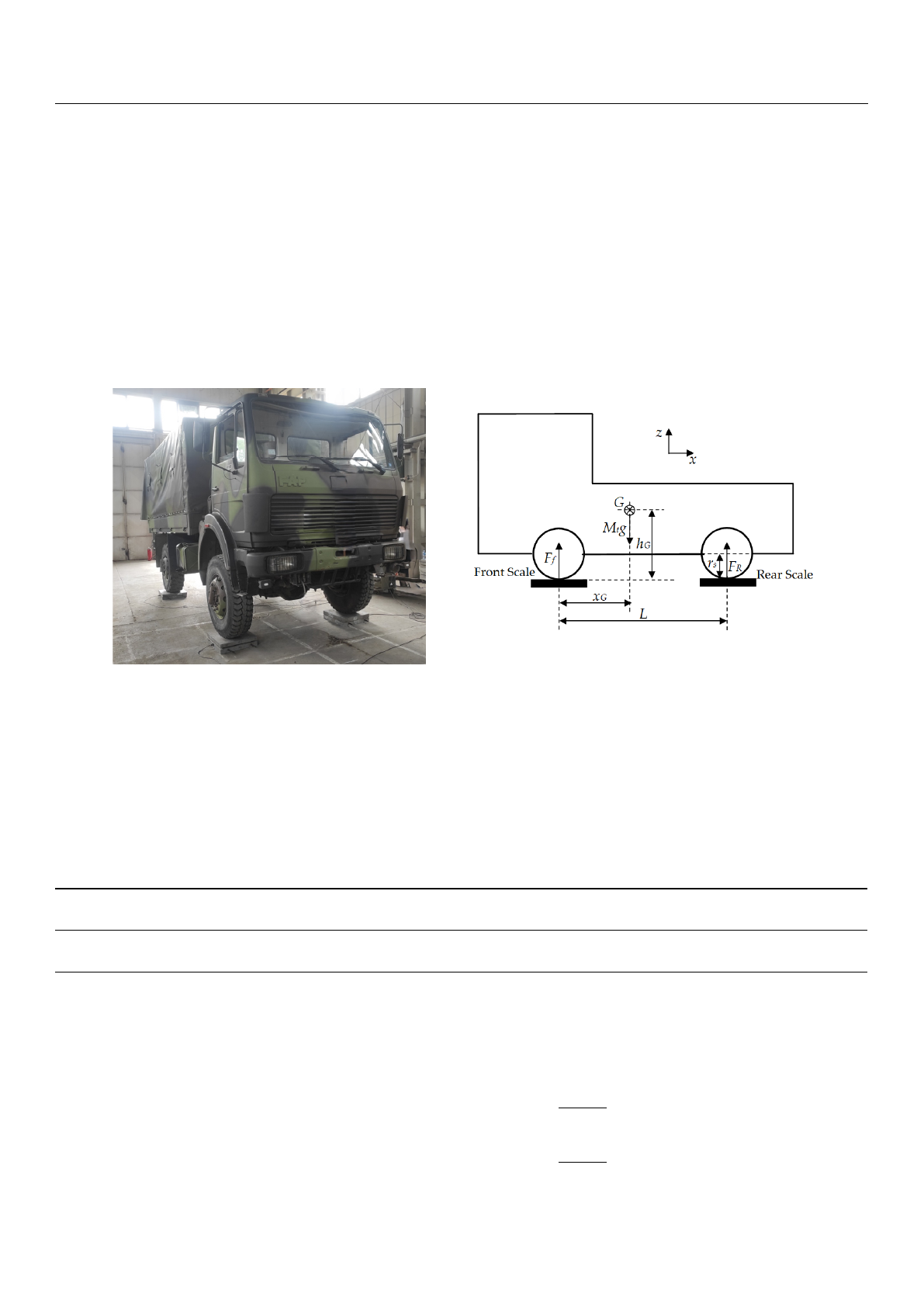
wheel, as shown in Figure 1. The mass readings obtained from each scale were recorded.
Appl. Sci. 2024, 14, x FOR PEER REVIEW 5 of 18
modeled, including leaf springs in each suspension. Due to their modeling complexity,
validation is achieved through a static experimental test. Finally, a full truck is modeled
and validated through the dynamic experimental test, with a focus on lateral dynamics.
The results show a good correlation between the simulated model and the real truck, con-
cluding that the truck model is validated in terms of lateral dynamics.
2. Experimental Measurement of Truck Characteristics
2.1. Determination of Truck Mass and Center of Gravity Coordinates
The purpose of this experiment was to measure the vehicle mass of the truck and the
position of its center of gravity in three directions. This experiment is divided into two
parts.
2.1.1. Determination of Vehicle Mass and the Coordinates of the Center of Gravity in the
Horizontal Plane (xG, yG)
This part of the experiment aimed to measure the mass of the truck Mt and identify
the position of its center of gravity in the horizontal plane (xG, yG). For this, two measure-
ment tests were conducted. The truck was placed on four scales in each test, one under
each wheel, as shown in Figure 1. The mass readings obtained from each scale were rec-
orded.
These values are essential for knowing the mass distribution in the front/rear axles
and left/right side of the truck denoted as mfront/mrear and mleft/mright, respectively, which al-
low the determination of the precise coordinates of the center of gravity in the horizontal
plane. Additionally, the wheelbase (L) and width (l) of the truck were measured.
(a) (b)
Figure 1. Truck measurements mass: (a) experiment; (b) schematic representation.
Table 1 presents the vehicle mass values from each scale for the two tests.
Table 1. Mass recorded by each scale.
Scales Position Front
Left
Front
Right
Rear
Left
Rear
Right
Vehicle
Mass
Mass
Average
Mass value
(kg)
T1 2120 2160 1360 1530 7170 7205
T2 2170 2210 1340 1520 7240
By applying Newton’s second law and using the data given in Table 1, the coordi-
nates of the center of gravity in the horizontal plane were calculated by Equations (1) and
(2), where xG coordinate determines the distance from the front axle, and yG coordinate the
distance from the left truck wheels:
Figure 1. Truck measurements mass: (a) experiment; (b) schematic representation.
These values are essential for knowing the mass distribution in the front/rear axles
and left/right side of the truck denoted as m
front
/m
rear
and m
left
/m
right
, respectively, which
allow the determination of the precise coordinates of the center of gravity in the horizontal
plane. Additionally, the wheelbase (L) and width (l) of the truck were measured.
Table 1presents the vehicle mass values from each scale for the two tests.
Table 1. Mass recorded by each scale.
Scales Position Front
Left
Front
Right
Rear
Left
Rear
Right
Vehicle Mass
Mass
Average
Mass value
(kg)
T1 2120 2160 1360 1530 7170 7205
T2 2170 2210 1340 1520 7240
By applying Newton’s second law and using the data given in Table 1, the coordinates
of the center of gravity in the horizontal plane were calculated by Equations (1) and (2),
where x
G
coordinate determines the distance from the front axle, and y
G
coordinate the
distance from the left truck wheels:
xG=mrear·L
Mt(1)
yG=mright·l
Mt(2)
Loading more pages...